Catalytic Converter: Service and Repair
Front Exhaust Pipe with Catalytic Converters and Front Muffler
Removing
- Remove the heated oxygen sensor (G39).
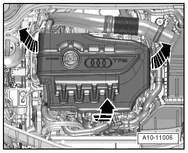
- Remove the engine cover - arrows -.
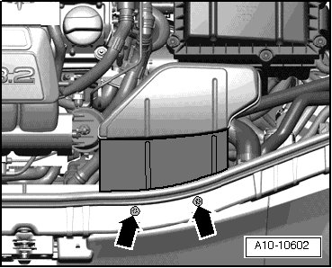
- Remove the bolts - arrows - and air guide.
- Remove the coolant hose by loosening the hose clamp - 1 -.
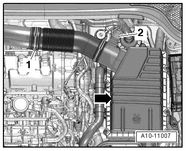
- Disconnect the connector - 2 - from the Mass Airflow (MAF) Sensor (G70).
- Detach upper section of air filter housing - arrow - and remove air filter insert.
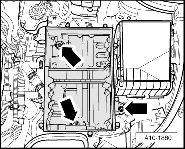
- Remove the bolts - arrows - and the lower section of the air filter housing.
- Remove bolt - arrow -.
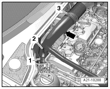
- Loosen the hose clamp - 1 - and lay the air guide pipe aside with the hose - 2 - connected.
• Ignore - 3 -.
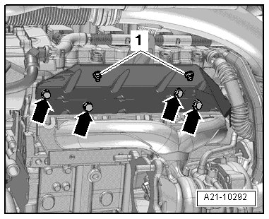
- Remove the bolts - arrows - and nuts - 1 - and then remove the heat shield.
- Remove the nuts - arrows - on the front exhaust pipe/turbocharger connection from the top.
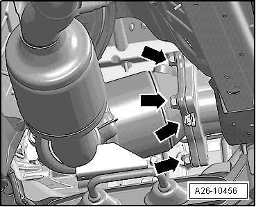
• The illustration shows the installation position from below.
- Mark position of flexible disc to bevel box flange for reinstallation.
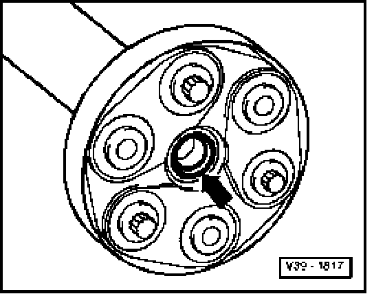
- Remove driveshaft flexible disc from bevel box - arrows - while counter holding on triangle flange with lever.
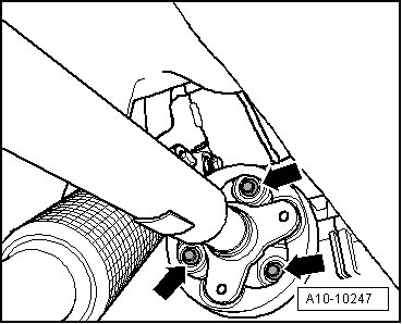
The shaft seal - arrow - in the driveshaft flange could be damaged.
• Press driveshaft horizontally as far back and to right side of vehicle as possible.
- Remove bolts - 1 - and - 2 - under the vehicle floor.
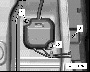
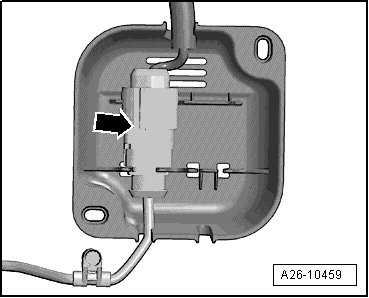
- Remove the cover from the oxygen sensor electrical connector bracket.
- Remove the bolt - 3 - and free up the electrical wire to the oxygen sensor.
- Remove the electrical connector - arrow - from the oxygen sensor after three way catalytic converter (G130) from the bracket and disconnect it.
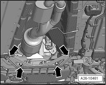
- Remove the bolts - arrows -, exhaust system bracket and tunnel brace.
Risk of damaging decoupling elements.
• Do not bend decoupling element in front exhaust pipe more than 10°.
- Disconnect the exhaust system at the clamping sleeve - arrows -.
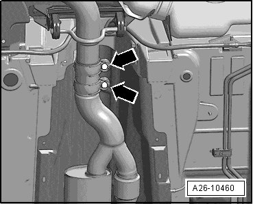
- Remove the front exhaust pipe with the catalytic converter and front muffler.
Installing
• For the correct tightening specifications, refer to => [ Muffler Overview ] Muffler Overview.
Installation is performed in reverse order of removal, noting the following.
• Replace seals and self-locking nuts.
• The hose supports, air guide pipes and hoses must be free of oil and grease before installing.
• Secure all hose connections with hose clamps appropriate for the model. Refer to the electronic parts catalog ETKA.
- Install exhaust system free of stress. Refer to => [ Exhaust System, Installing ] Removal and Replacement.