01J Continuously Variable Transmission
Electrical and Electronic Components and Component Locations
Data Link Connector (DLC)
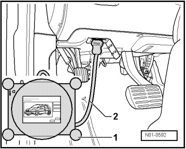
• Location: The diagnostic connection for the Vehicle Diagnosis, Testing and Information System (VAS 5051B) is located in the driver's side footwell.
Transmission control module (J217)
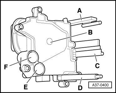
• Location: Transmission Control Module (TCM) (J217) is on the back end of transmission, secured directly to hydraulic control module.
The following components are integrated in Transmission Control Module (TCM) (J217):
A Transmission Output Speed (RPM) Sensor (G195) and Transmission Output Speed (RPM) Sensor 2 (G196)
B Transmission Fluid Temperature Sensor (G93)
C Multi-Function Transmission Range Switch (F125)
D Transmission Input Speed (RPM) Sensor (G182)
E Automatic Transmission Hydraulic Pressure Sensor 1 (G193)
F Automatic Transmission Hydraulic Pressure Sensor 2 (G194)
• Transmission Control Module (TCM) (J217) is monitored with On Board Diagnostics (OBD).
Transmission Control Module (J217), Removing and Installing => [ Transmission Control Module ] Service and Repair.
Hydraulic control module

• Location: Hydraulic control module is bolted to back end of transmission. The Transmission Control Module (TCM) (J217) is attached directly to the hydraulic control module.
A Automatic Transmission Pressure Regulating Valve 1 (N215) electrical connector
B Automatic Transmission Pressure Regulating Valve 2 (N216) electrical connector
C Solenoid Valve 1 (N88) electrical connector
Removing and installing hydraulic control module => [ Hydraulic Control Module ] Hydraulic Control Module.
Following valves are integrated into hydraulic control module (not depicted here).
• Automatic Transmission Pressure Regulating Valve 1 (N215) (clutch solenoid valve)
• Automatic Transmission Pressure Regulating Valve 2 (N216) (solenoid valve gear)
• Solenoid Valve 1 (N88) (clutch cooling/safety shut-off)
• Clutch cooling valve
• Minimum pressure valve
• Pressure relief valve
• Clutch control valve
• Pressure control valve
• Valves are monitored via On Board Diagnostic (OBD).
• Description and functions of individual valves 951003Continuously Variable Transmission (CVT) Multitronic 01J.
Selector Lever Sensor System Control Module (J587) and Tiptronic Switch (F189) - vehicles through 11.2005
• Location: The Selector Lever Sensor System Control Module (J587) and Tiptronic Switch (F189) are mounted to the shift mechanism function unit - arrows - as a unit - 1 -.
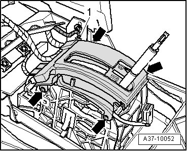
- => [ Selector Lever Sensor System Control Module with Tiptronic Switch ] Service and Repair.
Selector Lever Sensor System Control Module (J587) and Tiptronic Switch (F189) - vehicles from 11.2005
• Location: The Selector Lever Sensor System Control Module (J587) and Tiptronic Switch (F189) are clipped onto the shift mechanism function unit - arrows - as a unit - 2 -.
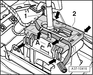
=> [ Selector Lever Sensor System Control Module with Tiptronic Switch ] Service and Repair.
Shift Lock Solenoid (N110) - vehicles through 11.2005
• Location: Shift Lock Solenoid (N110) - 1 - is clipped onto shift mechanism.
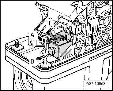
=> [ Shift Lock Solenoid ] Service and Repair.
Shift Lock Solenoid (N110) - vehicles from 11.2005
• Location: Shift Lock Solenoid (N110) - 1 - is clipped onto shift mechanism.
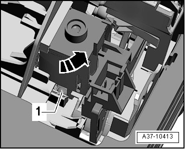
=> [ Shift Lock Solenoid ] Service and Repair
Transmission Park Selector Switch (F305) - vehicles through 11.2005
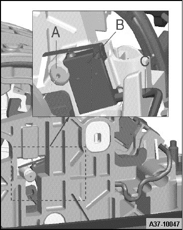
• Location: The Transmission Park Selector Switch (F305), which consists of 2 microswitches - 1 - and - 2 - is mounted on the right side of the selector mechanism.
=> [ Transmission Park Selector Switch ] Service and Repair
Transmission Park Selector Switch (F305) - vehicles from 11.2005
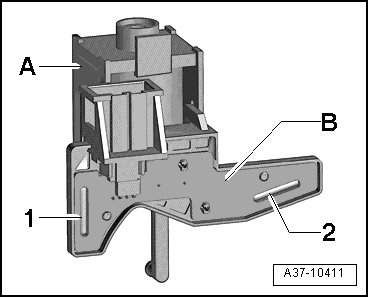
• Location: The Transmission Park Selector Switch (F305) consisting of two microswitches - 1 - and - 2 - plate is installed on the plate - B - on the Shift Lock Solenoid (N110) - A -.
The Transmission Park Selector Switch (F305) can only be replaced together with Shift Lock Solenoid (N110) => [ Shift Lock Solenoid ] Service and Repair,
Kick Down Switch (F8)
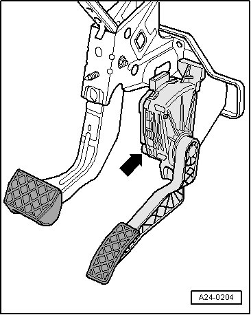
• Location: A specific value from the Throttle Position (TP) Sensor (G79) and the Accelerator Pedal Position Sensor 2 (G185) are stored in the engine control module.
Accelerator pedal position sensors are integrated in accelerator module - arrow -.
• If the throttle position sensor is faulty, then the accelerator pedal module must be replaced.
Selector Lever Position Display (Y6)
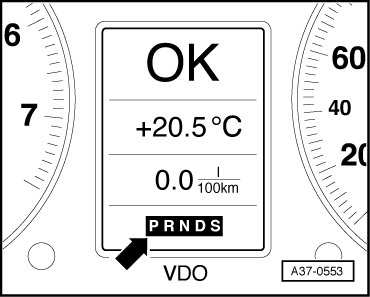
• Location: Transmission Range (TR) Display (Y6) is integrated in instrument cluster.
• A completely lit display warns of a simple fault.
• A blinking display warns of a critical fault.
• No display indicates a wiring fault or a faulty Transmission Range (TR) Display (Y6).
• If the Transmission Range (TR) Display (Y6) is faulty, then the instrument cluster must be replaced.
Selector Lever Transmission Range (TR) Position Display (Y26)
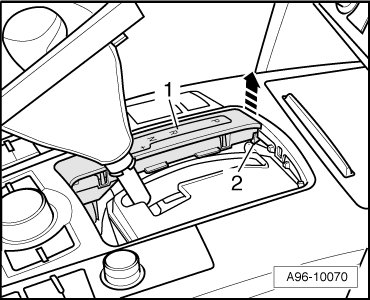
• Selector Lever Transmission Range (TR) Position Display (Y26) - 1 - is clipped into center console.
=> [ Selector Lever Transmission Range Position Display ] Service and Repair or => [ Selector Lever Transmission Range Position Display ] Service and Repair.