Steering Mounted Controls Communication Module: Service and Repair
Steering Column Switch Module and Electronic Ignition Switch
=> [ Steering Column Switch Module ]
=> [ Steering Column Electronic Systems Control Module (J527) ]
=> [ Steering Column Electronic Systems Control Module Connector Assignment ]
=> [ Turn Signal, Cruise Control, Windshield Wiper and Washer Intermittent Switch ]
=> [ Access/Start Authorization Switch ]
=> [ Access/Start Authorization Switch Connector Assignment ]
• The steering column switch module consists of the coil connector with slip ring, steering angle sensor (G85) , steering column switch (turn signal indicator switch, wiper switch, cruise control switch) and steering column electronic systems control module (J527).
• Fault finding is done in "Guided Fault Finding". Refer to the vehicle diagnosis, testing and information system VAS 5051.
Steering Column Switch Module
Removing
- Adjust the steering wheel downward and to the rear as far as possible, use the entire adjustment range of the steering column adjustment for this.
- Remove the driver airbag.
- Remove the steering wheel.
- Remove the steering column trim.
- Remove the bolt - 1 -.
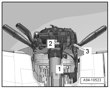
- Disconnect the electrical connector - 2 -.
The technician must discharge static electricity before disconnecting the electrical connector - 3 -, for example by touching the door striker pin.
- Disconnect the electrical connector - 3 -.
- Press the catch - 1 - in the - direction of the arrow - until the harness connector - 2 - disengages.
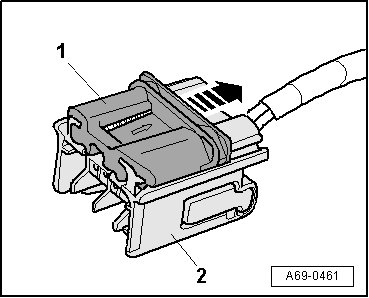
- Carefully remove the steering column switch module.
Installing
• Tightening specification, refer to => [ Steering Column Switch Module and Electronic Ignition Lock Overview ] Service and Repair.
Install in reverse order of removal, observing the following:
- Install the steering column trim.
- Install the steering wheel.
- Install the driver airbag.
Steering Column Electronic Systems Control Module (J527)
The airbag spiral spring/return spring with slip ring (F138) and the steering angle sensor (G85) are integrated in the steering column electronic systems control module (J527).
- If the control module was replaced, select the "Replace" function for the respective control module in "Guided Fault Finding" or "Guided Functions" using the Vehicle Diagnostic Tester.
Removing
• The steering wheel must be centered (wheels in straight ahead position) when removing and installing the coil connector with slip ring.
- Adjust the steering wheel downward and to the rear as far as possible, use the entire adjustment range of the steering column adjustment for this.
- Remove the driver airbag.
- Remove the steering wheel.
- Remove the steering column trim.
- Remove the bolt - 1 -.
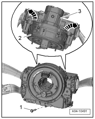
- Release the retaining hooks - arrows - carefully and remove the airbag spiral spring/return spring with slip ring - item 2 - from the steering column switch module - 3 -.
- Release the electrical connectors on the airbag spiral spring/return spring with slip ring - item 3 - by positioning the screwdriver at the retaining hooks - 2 and 4 - as illustrated and carefully releasing the connectors - 1 and 5 - in the - direction of arrow A -.
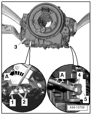
- Remove the airbag spiral spring/return spring with slip ring on the steering column switch module.
Installing
Install in reverse order of removal, observing the following:
- Make sure all retaining hooks and connectors are engaged securely.
- Install the steering column trim.
- Install the steering wheel.
- Install the driver airbag.
- The steering angle sensor must be adapted in "Guided Fault Finding" or "Guided Functions" after replacing the airbag spiral spring/return spring with slip ring. Refer to the Vehicle Diagnostic Tester.
Steering Column Electronic Systems Control Module Connector Assignment
• The steering column electronic systems control module (J527) is part of the complete system "steering column switch module". and receives signals from steering column switch, for example.
• Check the steering column electronic systems control module in "Guided Fault Finding". Refer to the vehicle diagnosis, testing and information system VAS 5051.
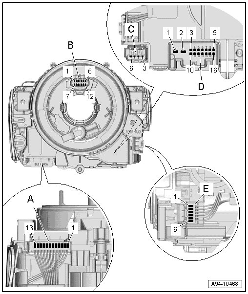
A - Connector, Turn Signal Switch/ Cruise Control
1 - Cruise control lever ground
2 - Cruise control set
3 - ACC
4 - Cruise control Res ("+")/Set ("-")
5 - Voltage supply (terminal 15)
6 - Cruise control ground/turn signal switch
7 - Cruise control "off"
8 - Cruise control Res/Soft
9 - Radio (AIA)
10 - Headlamp flasher
11 - High beams
12 - Turn signal switch
13 - Ground, turn signal switch
B - Connector, Spiral Spring/Airbag/Multifunction Steering Wheel/Signal Horn
1 - Ground (GND)
2 - Horn signal
3 - Airbag 1 "+"
4 - Airbag 1 "-"
5 - Airbag 2 "+"
6 - Airbag 2 "-"
7 - Tip down
8 - Terminal 30
9 - LIN
10 - Tip up
11 - Dimming (terminal 58s)
12 Tip ground
C - Connector, Airbag Control Module
3 - Airbag 1 "-"
4 - Airbag 1 "+"
5 - Airbag 2 "+"
6 - Airbag 2 "-"
D - Connector, Electrical System
1 - Not used
2 - Not used
3 - Voltage supply terminal 30
4 - Powertrain Controller Area Network (CAN) bus shielding
5 - Cruise control latched Off
6 - Not used
7 - Radio/radio button
8 - Comfort CAN bus Low
9 - Comfort CAN bus High
10 - Voltage supply terminal 31
11 - Powertrain CAN bus High
12 - Powertrain CAN bus Low
13 - Signal, electronic ignition switch, terminal 15
14 - Not used
15 - Not used
16 - Not used
E - Connector, Wiper System/DIS
1 - Windshield washer ground
2 - Windshield wiper switch
3 - Wash
4 - DIS signal
5 - Intermittent wipe potentiometer
6 - DIS ground
Turn Signal, Cruise Control, Windshield Wiper and Washer Intermittent Switch
Removing
- Remove the steering column switch module. Refer to => [ Steering Column Switch Module ].
- Remove the steering column electronic systems control module (J527). Refer to => [ Steering Column Electronic Systems Control Module (J527) ].
- Remove the turn signal switch (E2) , cruise control switch (E45) and windshield wiper/washer switch (E22).
Installing
Install in reverse order of removal, observing the following:
- Install the steering column electronic systems control module. Refer to => [ Steering Column Electronic Systems Control Module (J527) ].
- Install the steering column switch module. Refer to => [ Steering Column Switch Module ].
Access/Start Authorization Switch
• Induction coil for immobilizer is secured to the access/start authorization switch (E415) and cannot be replaced separately.
• If induction coil is malfunctioning, the access/start authorization switch must be replaced.
• The immobilizer does not need to be adapted if the access/start authorization switch is replaced.
• The lock in the access/start authorization switch is not coded mechanically.
• The keys must therefore not be replaced when the access/start authorization switch is replaced; present keys continue to match.
Special tools, testers and auxiliary items required
• Special Pliers (VAS 6339)
Removing
- Remove the driver side instrument panel cover.
- Remove the right impact bar.
- Remove the Multi Media Interface (MMI) screen cover.
- Remove the instrument cluster gap cover.
- Remove the bolt - 2 - for the trim - 1 -.
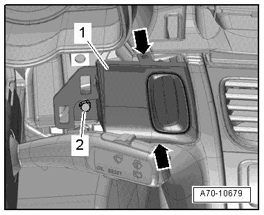
- Insert the (VAS 6339) through the trim flaps.
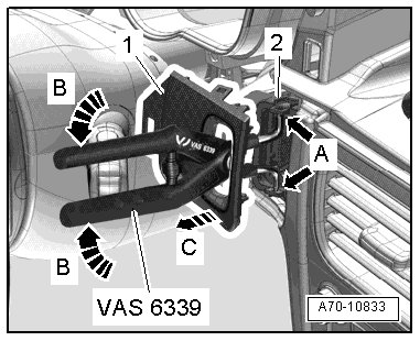
- Position the tips of the (VAS 6339) on both holes - A arrows - on the access/start authorization switch - 2 -.
- Press the (VAS 6339) together - B arrows - to spread the tips of the pliers and release the trim retaining tabs.
- Hold the (VAS 6339) pressed with one hand and remove the trim - 1 - with the other hand - arrow C -.
• Only use the (VAS 6339) to release the trim. Remove the trim by hand.
- Remove the bolt - 2 -.
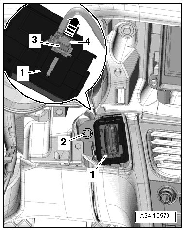
- Remove the access/start authorization switch - 1 - forward toward the driver footwell and out of the instrument panel.
- Disconnect the connector - 3 - by sliding the retainer - 4 - up - arrow - and pressing the release.
Installing
• Tightening specification, refer to => [ Access/Start Authorization Switch Bolt Tightening Specification ] Service and Repair.
Install in reverse order of removal, observing the following:
- Install the instrument cluster gap cover.
- Install the MMI screen cover.
- Install the right impact bar.
- Install the driver side instrument panel cover.
Access/Start Authorization Switch Connector Assignment
Connector
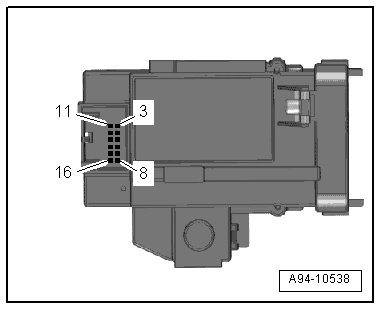
3 Not used
4 Not used
5 S-contact
6 Terminal 15
7 LIN
8 Terminal 30
9 Not used
10 Not used
11 Not used
12 Not used
13 RED2, terminal 15
14 RED, terminal 15
15 Ignition/starter switch +
16 Terminal 31