Data Bus On Board Diagnostic Interface (J533)
Data Bus On Board Diagnostic Interface (J533)
Special tools, testers and auxiliary items required
• Protective Cap For Cable Connector (VAS 6223/9) from Fiber Optic Plier Repair Set (VAS 6223)
- If the control module was replaced, select the "Replace" function for the respective control module in "Guided Fault Finding" or "Guided Functions". Refer to the vehicle diagnostic tester.
Removing
- Turn off the ignition and remove the ignition key.
- Remove the glove compartment.
- Remove the bolt - 2 -.
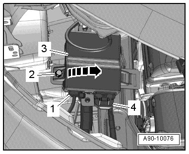
- Pivot the data bus on board diagnostic interface - item 3 - out of the bracket - arrow -.
- Disconnect the electrical connector - 4 -.
- Disconnect the fiber optic cable connector - 1 -.
- Seal the open wiring harness fiber optic connector - 2 - using the (VAS 6223/9) - item 1 -.
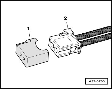
• The (VAS 6223/9) prevents contamination of, or mechanical damage to, the end face of the fiber optic cable which would impair signal transmission.
Installing
• Tightening specifications, refer to => [ Data Bus On Board Diagnostic Interface Overview ] Data Bus On Board Diagnostic Interface Overview.
Install in reverse order of removal, observing the following:
- Install the glove compartment.
- Follow the instructions on the vehicle diagnostic tester display with a new data bus on board diagnostic interface.