Hydraulic Control Module
Hydraulic Control Module
Removing
• Refer to => [ Repair Information ] Repair Information.
• Refer to => [ Clean Working Conditions ] Clean Working Conditions.
• End cover removed, refer to => [ Cover, with Transmission Removed ] Cover, With Transmission Removed.
• Transmission control module (J217) removed, refer to => [ Transmission Control Module (J217) ] Transmission Control Module (J217).
Danger of damaging the spring.
• Do not remove or install the spring using sharp edged pliers or something similar.
• If the spring wire gets damaged through notches or bends, the slider for selector lever position will not function correctly.
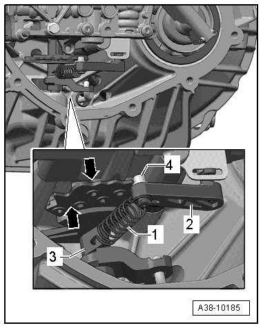
- Unhook the spring - 1 - on the slider for selector lever position - 2 - and on the selector shaft - 3 -.
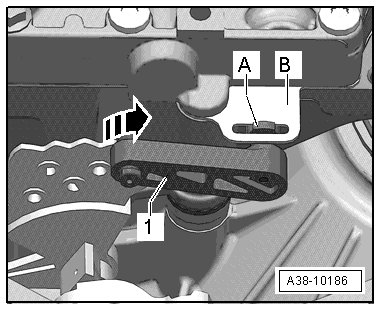
- Move the selector lever lock mechanism - 1 - to the right - arrow -. The tab - A - will be removed through the slit on the retaining plate - B -.
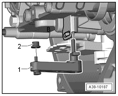
- Pull the selector lever lock mechanism lever - 1 - downward out of bearing hole in the hydraulic control module. When doing this, pay attention to the roller - 2 -.
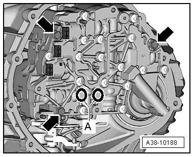
- Remove the bolts - arrows -.
Danger of damaging the hydraulic control module.
• The hydraulic control module must not, under any circumstances, be supported on the long pump shaft on the back side or raised up.
• Otherwise, the blades inside the pump will be crushed and the pump will get damaged. Likewise the bearing for the pump shaft will get damaged.
- Carefully remove the hydraulic control module toward the rear and tilt it downward so that it is possible to remove the long pump shaft.
• Ignore - A -.
- Remove the axial sealing elements - A and B - from the transmission.
Installing
Install in reverse order of removal. Note the following:
• For the correct tightening specifications, refer to => [ Cover, Transmission Control Module and Hydraulic Control Unit Overview ] Cover, Transmission Control Module and Hydraulic Control Unit Overview.
• Always replace a dirty or faulty hydraulic control module.
• Replace gaskets and O-rings.
- Replace the axial sealing elements - A - (quantity: 3) and - B -.
• Installed position: The axial sealing elements - A - must be installed with the sealing lips facing upward, as illustrated.
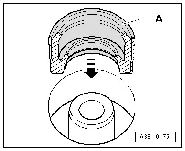
• The color identification on the upper edge must be visible.
- Coat the axial sealing elements with ATF before installing - arrow -.
- Push the gearshift lever - 2 - in direction of - arrow - all the way forward so that the shifting cam - 1 - is almost vertical (slightly angled to the right).
- Press control piston - B - on the back of the hydraulic control module outward (to the right) until it engages into the assembly spring - A -.
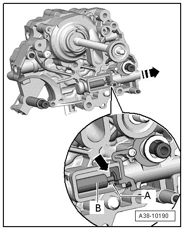
- With the pump shaft facing forward, install the hydraulic control module tilted downward into the transmission.
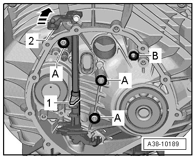
• When installing control module, make sure that shifting cam (item 1 in Fig. A38-10189 ) engages into free groove - arrow - on control piston - B -.
Danger of damaging the hydraulic control module.
• If the bolts are tightened to the specification while shifting the cam or the control piston was incorrectly set, the hydraulic control module will get damaged.
- Install the bolts - arrows - hand-tight.
Checking the Function of the Control Piston
- Move the gearshift lever - A - several times forward and backward - arrow 1 -.
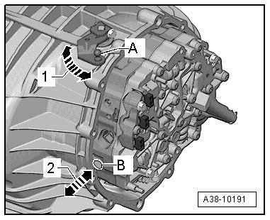
• When doing this, the control piston - B - must travel outward and inward accordingly - arrow 2 -.
If control piston does not move, shifting cam has not engaged into groove - arrow - at control piston on rear side of hydraulic control module. In this case:
- Remove the hydraulic control module again.
Check for Damage Possibly Caused by an Incorrect Installation:
• It must be possible to easily move the control piston - B - left and right; if not, replace the hydraulic control module.
• The shifting cam - 1 - or the selector shaft must have no damage due to an incorrect installation.
- Install the hydraulic control module.
The control piston moves as described:
- Tighten the bolts - arrows - to the tightening specification.
Install the Slider for Selector Lever Position
- Install the roller - 2 - with the shoulder of the selector lever lock mechanism lever - 1 - on the lever.
- Slide the selector lever lock mechanism lever - 1 - into the bearing hole in the hydraulic control module housing.
- Move the selector lever lock mechanism lever - 1 - to the left opposite the direction of - arrow -, by doing this, the retaining tab - A - will turn in the slot in the retaining plate and - B - will be held there.
Danger of damaging the spring.
• Do not remove or install the spring using sharp edged pliers or something similar.
• If the spring wire gets damaged through notches or bends, the slider for selector lever position will not function correctly.
- Install the spring - 1 - into the selector shaft - 3 - and the selector lever lock mechanism lever - 1 -.
Installation position of the spring - 1 -:
• The bent end of the spring must be attached to the selector shaft - 3 -.
• The round end of the spring must engage into the selector lever lock mechanism - 2 -.
- Move the gearshift lever - A - all the way forward and backward - arrow 1 -.
• Ignore - arrow 2 - and - B -.
• The detent plate - upper arrow - moves to the left and to the right.
• When doing this, it must allow the roller - 4 - to engage in the individual notches.
• The roller must be installed with the collar facing down so that it cannot be removed upward.
- Install the transmission control module. Refer to => [ Transmission Control Module (J217) ] Transmission Control Module (J217).
The following must be performed with a vehicle diagnosis tester if the hydraulic control module was replaced:
- Select the following menu options under "Functions/Component Selection" in Guided Fault Finding on the vehicle diagnosis tester :
• Drive
• 0AW transmission
• 01-On Board Diagnostic (OBD) capable systems
• 02-Transmission electronics
• 02-Transmission electronics, functions
• 02-Replace the hydraulic control module