Front Suspension
Subframe
Special tools, testers and auxiliary items required
• Torque Wrench 5-50 Nm (V.A.G 1331)
• Torque Wrench 40-200 Nm (V.A.G 1332)
• Engine-/Gearbox Jack (V.A.G 1383 A) with Universal Transmission Support (V.A.G 1359/2)
• Tensioning Strap (T10038)
• Wheel Hub Support (T10149)
• Hose Clamps Up to 25 mm Dia. (3094)
• Vehicle Diagnosis Tester
Removing
- Place the vehicle on a hoist. Refer to => [ Raising and Lowering ] Description and Operation.
- Vehicle with air suspension, bleed the system using a vehicle diagnosis tester.
- Remove the engine cover.
- Support the engine entirely using the engine support bridge.
- Remove the front wheels.
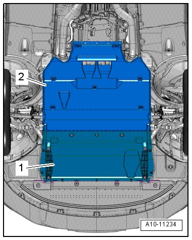
- Remove the noise insulation - 1 and 2 -.
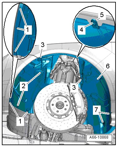
- Remove the front left and right wheel housing liners.
- Remove the nuts - 3 - and remove the cover - 2 - (if equipped) from the right and left drive axle.
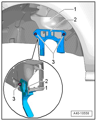
- Tip the top of the cover - 2 - toward the outside and guide it downward by the seam - 1 -.
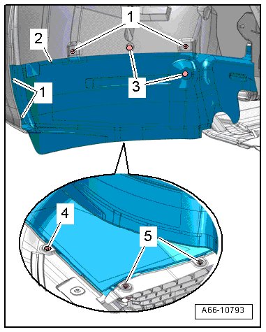
- Remove the left and right wheel spoilers.
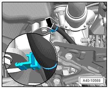
- Disconnect the left and right connector - 1 - from the vehicle level sensor (if equipped) and remove the clip - arrow -.
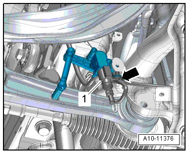
- Remove the right and left clamps for the vehicle level sensor wires from the subframe.
- Remove the connector - 1 - for the vehicle signals (CAN-Bus and terminal 15) from the power steering control module (J500).
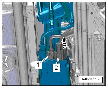
- Releases the retainer - arrow -, push the release down and disconnect the connector - 2 - for the voltage (terminal 30) from the power steering control module.
- Free up the clip - arrow -, disconnect the connector - 1 - and free up the electric wire.
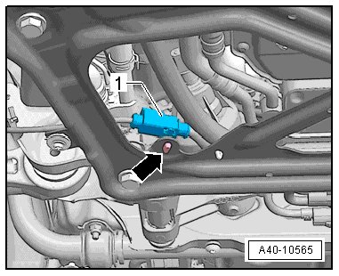
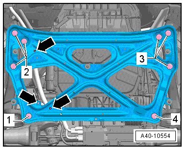
- Remove the remaining clips - arrows - on the crossbrace and free up the wiring harness.
- Open the clip - arrow - on the left rear subframe and free up the wiring harness.
- Turn the steering wheel so that the wheels are in the straight-ahead position and then tape it secure - arrow - so that it cannot turn.
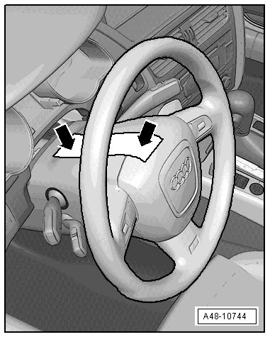
• Be sure to use tape that will not leave behind any residue when it is removed.
• Be careful not to turn the steering wheel during the repair other the airbag spiral spring/return spring with slip ring (F138) will get damaged.
- Remove bolt - arrow -.
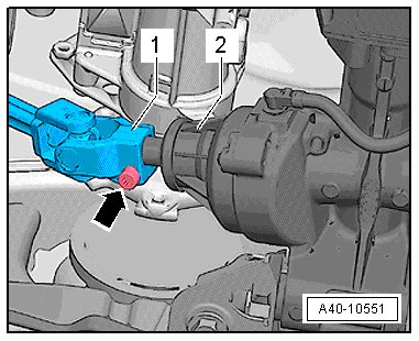
- Remove the universal joint - 1 - from the steering gear - 2 - and support the steering intermediate shaft so that it cannot fall.
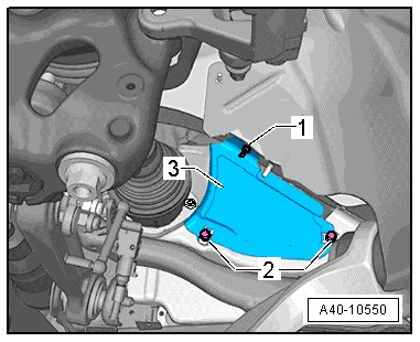
- Remove the right and left nuts - 1 - and bolts - 2 - and remove the heat shield upper section - 3 -.
- For vehicles with an intermediate flange - 1 -, remove the bolts - 2 and 3 - and free up the intermediate flange with the hoses still connected.
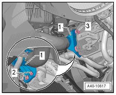
- Tie up the left and right wheel bearing housings using the (T10038) - 1 -, as illustrated.
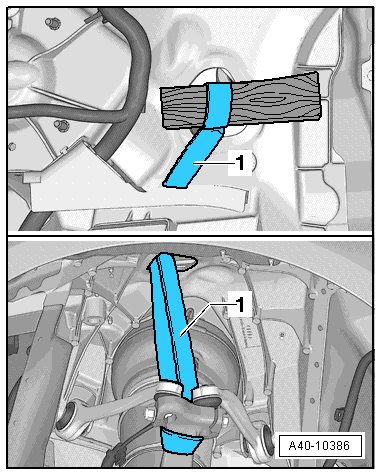
• To prevent the joints on the upper control arm from being damaged, support the wheel bearing housing.
- Remove the left and right control arms. Refer to => [ Track Control Arm ] Track Control Arm.
- Remove the nut from the left and right guide link joint pins enough so it is flush with the joint pin threads. Counter hold the joint pins if necessary.
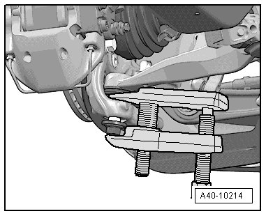
- Press linkage stub of guide control arm off conical seating using (T40042).
• Be careful not to damage CV boot in the process!
• Make sure that both puller lever arms are parallel to each other when using greatest force.
- Separate the left and right guide link from the wheel bearing housing. Be careful not to damage the CV boot on the guide link joint pin.
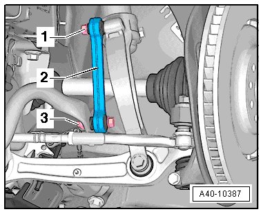
- Remove the threaded connector - 1 - for the right and left coupling rods on the shock absorber fork.
- Disconnect and free up the connectors - 1 - from the right electrohydraulic engine mount solenoid valve (N145) and - 2 - and from the left electrohydraulic engine mount solenoid valve (N144).
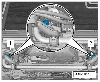
Applies to Vehicles with a 6-Cylinder Engine
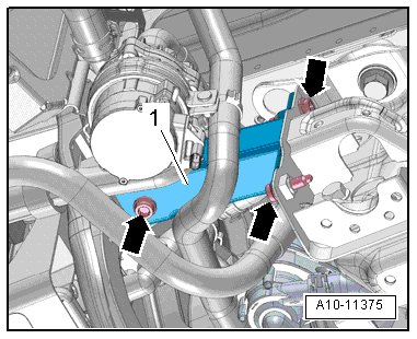
- Remove the bolts - arrows - and the left lower front longitudinal member - 1 -.
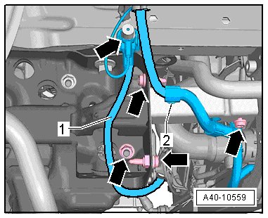
- Remove the nuts and bolts - arrows - and free up the ground cable - 1 - and the electric wire - 2 -.
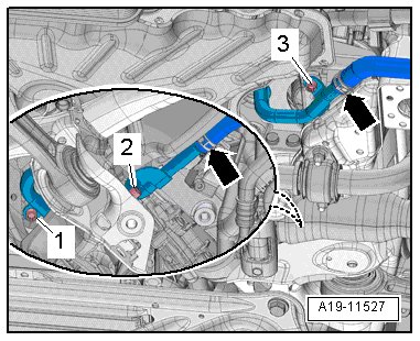
- Remove the right lower front longitudinal member - 1 -.
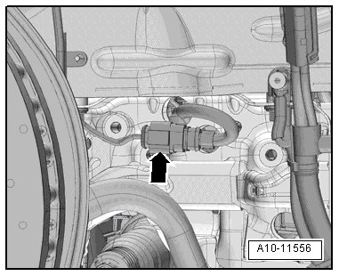
- Loosen the hose clamps - arrows - to disconnect the coolant hose with the (3094) and remove it.
- Disconnect the left and right connectors - 1 and 2 -.
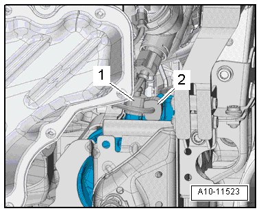
- Remove the connector - arrow - from the mount, disconnect it, and guide it through the subframe.
Continuation for All
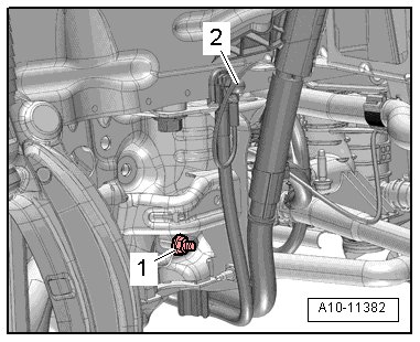
- Remove the nuts - 1 and 2 -, if necessary, and move the ground cable - arrow - to the side.
- Remove the clip - arrow - from the engine mount bracket and free up the wires and the metal bracket - 1 -.
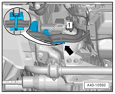
• There is also a wire attached to the rear engine bracket on the left, depending on the engine type.
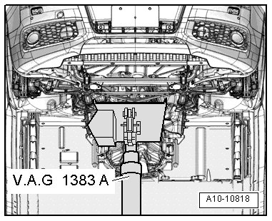
- Support the subframe using the (V.A.G 1383 A) and a piece of hard wood.
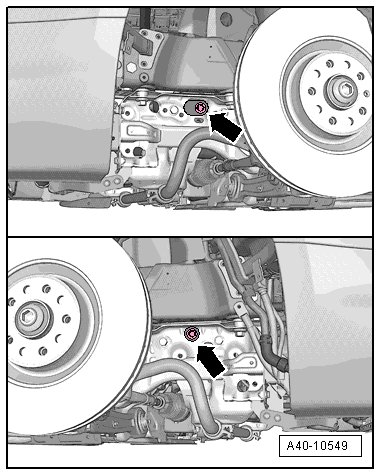
- Remove the bolt - arrow - for the left and right engine mounts.
- Mark the installed position of the subframe on the longitudinal members using a felt-tip pen.
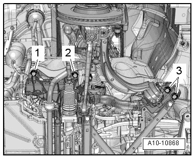
- Remove the left and right bolts - 1, 2 and 3 - from the subframe diagonally and in steps.
- Lower the subframe using the (V.A.G 1383 A).
• Make sure there is enough clearance for the electric lines when lowering the subframe.
• Replace the attachments later if necessary.
Installing
Install in reverse order of removal. Note the following:
Tightening specifications, refer to => [ Subframe, Crossbrace, Stabilizer Bar, Coupling Rod and Subframe Heat Shield Overview ] Subframe, Crossbrace, Stabilizer Bar, Coupling Rod and Subframe Heat Shield Overview.
Tightening specifications, refer to => [ Air Spring Damper/Steel Spring Damper, Shock Absorber Fork, Upper Control Arm and Tower Brace Overview ] Air Spring Damper/Steel Spring Damper, Shock Absorber Fork, Upper Control Arm and Tower Brace Overview.
Tightening specifications, refer to => [ Track Control Arm, Ball Joint, Guide Link and Level Control System Sensor Overview ] Track Control Arm, Ball Joint, Guide Link and Level Control System Sensor Overview.
Tightening specifications, refer to => [ Electromechanical Steering Gear with Tie Rods Overview ] Electromechanical Steering Gear With Tie Rods Overview.
• Perform a pre-adjustment on the subframe if it is being replaced or if it had to be removed in order to loosen the crossbrace.
Subframe Pre-Adjusting Procedure
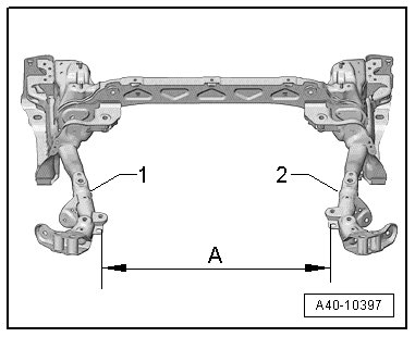
1. Place the subframe over the head.
2. Pre-install the steering gear and guide link (tighten the bolts hand-tight).
3. Move the arms - 1 and 2 - to adjust dimension - A - (the inner edges of the holes must match up with each other).
4. Mount the crossbrace and tighten it to the rear bolting points. The crossbrace is now pre-adjusted.
5. Tighten the steering gear.
6. Tighten the crossbrace at the front 2 attaching points.
Dimension - A - = 599 mm
• Bonded rubber bushings can only be turned to a limited extent. Only tighten suspension bolts when vehicle is in curb weight or control position.
• Lift wheel bearing in control position. Refer to => [ Wheel Bearing, with Air Suspension, Lifting to Curb Weight Position ] Wheel Bearing, With Air Suspension, Lifting to Curb Weight Position or => [ Wheel Bearing, with Coil Spring, Lifting to Curb Weight Position ] Wheel Bearing, With Coil Spring, Lifting to Curb Weight Position.
- Position the subframe on the body at the location marked.
- Tighten the subframe bolts diagonally.
All bolts and nuts must be tightened properly before driving the vehicle!
- Axle alignment is required, see table. Refer to => [ Wheel Alignment ] Wheel Alignment.
- On vehicles with automatic headlamp range control system, perform a basic setting on the headlamps.
- If the vehicle level sensor was removed and installed on a vehicle with air suspension or if the linkage rod was loosened, then it is necessary to adapt the control position. Use a vehicle diagnosis tester and diagnostic cable in "Guided Functions".
- If the control position was reprogrammed on vehicles with lane assist, the camera control module (J852) must be calibrated again. Refer to => [ Camera Control Module (J852), Lane Assist, Calibrating ] Testing and Inspection.