Transfer Fuel Pump Electrical & Module, Testing
Transfer Fuel Pump Electrical & Module, Testing
Special tools, testers and auxiliary items required
• Multimeter.
• Electrical connector test lead set.
Test conditions
• Battery voltage 12.5 V.
• Fuse 3 in Fuse Panel C is OK.
• Fuel filter OK.
• Ignition switched off.
• The Fuel Pump Control Module is between floor panel and fuel delivery unit (right-side).
• The Fuel Pump Control Module is mounted with retainers that need to be removed for accessing the module and harness. Refer to the Repair Manual for removal procedure.
• When the door is opened the fuel pump is activated for 2 seconds to build up the pressure in the fuel system.
• Models with an airbag are installed with a fuel shut - off system. It reduces the danger of a fire in a crash as the fuel pump is switched off via the fuel pump relay.
• Cover the fuel tank opening with a clean cardboard box to prevent dirt from falling into Gas Tank
Test procedure
- Perform a preliminary check to verify the customers complaint. Refer to => [ Preliminary Check ] Preliminary Check
Start diagnosis
- Switch ignition ON.
• The Transfer Fuel Pump runs quietly. Avoid surrounding noises while testing the fuel pump.
Specified value: Fuel Pump On for 2 seconds
- Switch the ignition OFF.
If the specified value was obtained:
- Condition may be intermittent
- Check the wiring for an open, high resistance or short to ground.
- Check the electrical harness connector for damage, corrosion, loose or broken terminals.
- If necessary, repair the faulty wiring connection.
- Go to Final procedures
If the specified value was Not obtained:
- Remove the rear seat bench. Refer to the appropriate service manual.
- Remove the fuel delivery unit cover located under the right rear seat. Refer to the Repair Manual for seat removal.
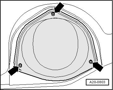
- Remove the Fuel Pump Control Module from the retaining clips on the floor sealing cover. - Arrows -
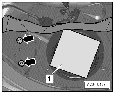
- Disconnect the electrical harness connector from the Fuel pump control module (J538). - 1 -
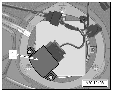
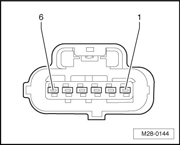
- Connect the Multimeter ground lead to terminal 4 of the Fuel Pump (FP) Control Module (J538) harness connector.
- Connect the Multimeter positive lead to terminal 5 of the Fuel Pump (FP) Control Module (J538) harness connector.
- Switch the Ignition ON.
Specified value: Battery voltage
- Switch the Ignition OFF.
If the specified value was Not obtained:
- Check the wiring from the Fuel Pump (FP) Control Module (J538) electrical harness connector terminal 5 to Fuse (SB 2) in Fuse Panel B for an open circuit or a short circuit to Ground (GND), also connector terminal 4 for a open circuit to Ground (GND).
- Check the electrical harness connector for damage, corrosion, loose or broken terminals.
- If necessary, repair the faulty wiring connection.
- Repair the circuit and replace any open fuses.
- Go to Final procedures
If the specified value was obtained:
- Disconnect the electrical harness connector from the Fuel Pump (FP) Control Module (J538) to the Transfer Fuel Pump (FP) (G6) - 1 -fuel delivery unit.
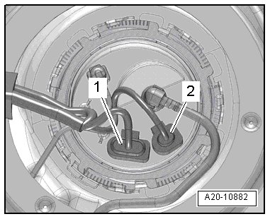
- Connect the Multimeter positive lead to terminal - 3 - of the Fuel Delivery Unit harness connector.
- Connect the Multimeter ground lead to terminal - 4 - of the Fuel Delivery Unit harness connector.
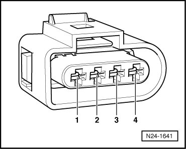
- Crank the engine and note voltage displayed on Multimeter during cranking.
Specified value: Voltage should be within 2 volts of battery voltage.
- Switch the ignition OFF.
- Continue test according to the following table:

Checking wiring
Checking Ground (GND)
- Using a Multimeter, check the Fuel Pump (FP) Control Module (J538) wiring harness to the Engine control module (J623) , connector T94 for resistance.

Specified value: 1.5 ohms or Less
If the specified value was Not obtained:
- Check for an open circuit
- Check the electrical harness connector for damage, corrosion, loose or broken terminals.
- If necessary, repair the wiring connection.
- Go to Final procedures
If the specified value was obtained:
- Replace the Fuel Pump (FP) Control Module (J538). Refer to the appropriate service manual.
- Perform a road test to verify repair.
If the fault does not return:
Repair complete, Generate readiness code. Refer to => [ Readiness Code ] Programming and Relearning.
If the fault does return and no malfunction is detected in the wiring and the voltage supply was OK:
- Replace the Engine Control Module (ECM) (J623). Refer to the appropriate service manual.
- Go to Final procedures
Checking wiring
- Connect a jumper cable from an Electrical connector test lead set to positive lead to terminal - 1 - of the Fuel Delivery Unit harness connector.
- Connect a jumper cable from an Electrical connector test lead set to Ground (GND) lead to terminal - 4 - of the Fuel Delivery Unit harness connector..
- Press switch on the hand - held remote control (jumper).
• The Fuel Pump (FP) runs quietly. Avoid surrounding noises while testing the fuel pump.
- Specified value: Listen for the transfer fuel pump noise, pump should be running.
If the specified value was not obtained:
- Remove the fuel delivery unit.
- Check the electrical wires between the locking flange and the fuel pump to make sure they are connected and routed correctly.
- If no fault is detected in the electrical wires, replace the Transfer Fuel Pump (FP) (G6). Refer to the Repair Manual for Proper replacement
- Go to Final procedures
If the specified value was obtained:
- Condition may be intermittent
- Check the wiring for an open, high resistance or short to ground.
- Check the electrical harness connector for damage, corrosion, loose or broken terminals.
- If necessary, repair the faulty wiring connection.
Final procedures
- Reinstall the fuel delivery unit cover located under the right rear seat.
- Reinstall the rear seat bench. Refer to the appropriate service manual.
- After the repair work, the following work steps must be performed in the following sequence:
1. Check the DTC memory. Refer to => [ Diagnostic Mode 03 - Read DTC Memory ] Diagnostic Modes 01 - 0A.
2. If necessary, erase the DTC memory. Refer to => [ Diagnostic Mode 04 - Erase DTC Memory ] Diagnostic Modes 01 - 0A.
3. If the DTC memory was erased, generate readiness code. Refer to => [ Readiness Code ] Programming and Relearning.