Ignition System: Service and Repair
Ignition Assembly Overview
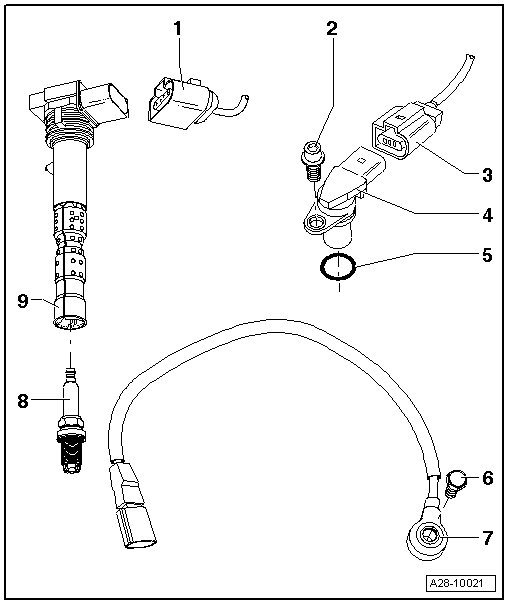
1 - Ignition Coil Connector
• 4-pin
2 - Bolt
• 10 Nm
3 - 3-Pin Connector
4 - Camshaft Position Sensor
• Camshaft position sensor (G40) cylinder bank 1
• Camshaft position sensor 3 (G300) cylinder bank 1
• Camshaft position sensor 2 (G163) cylinder bank 2
• Camshaft position sensor 4 (G301) cylinder bank 2
• Removing and installing, refer to => [ Camshaft Position Sensor ] Service and Repair
5 - O-ring
• Replace if damaged
• Coat with clean engine oil
6 - Bolt
• 20 Nm
• Tightening specifications affect function of Knock Sensor
7 - Knock Sensors
• Contact surfaces between knock sensor and cylinder block must be free of corrosion, dirt and grease
• Knock sensor 1 (G61) cylinder bank 1
• Knock sensor 2 (G66) cylinder bank 1
• Knock sensor 3 (G198) cylinder bank 2
• Knock sensor 4 (G199) cylinder bank 2
• Removing and installing, refer to => [ Ignition Coils ] Service and Repair
8 - Spark Plug
• 30 Nm
9 - Ignition coil
• Ignition coil 1 with power output stage (N70)
• Ignition coil 2 with power output stage (N127)
• Ignition coil 3 with power output stage (N291)
• Ignition coil 4 with power output stage (N292)
• Ignition coil 5 with power output stage (N323)
• Ignition coil 6 with power output stage (N324)
• Ignition coil 7 with power output stage (N325)
• Ignition coil 8 with power output stage (N326)
• Removing and installing, refer to => [ Ignition Coils ] Service and Repair
• To remove, use the ignition coil puller (T40039)