ABS Hydraulic Unit With ABS Control Module J104 Assembly Overview
ABS Hydraulic Unit with ABS Control Module J104 Assembly Overview
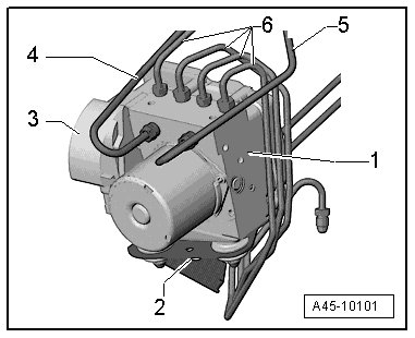
1 - ABS Hydraulic Unit (N55) with ABS Control Module (J104)
• Component location: In the left of the engine compartment.
• Removing and Installing, refer to => [ ABS Hydraulic Unit N55 with ABS Control Module ] Service and Repair.
• The hydraulic control unit is comprised of the ABS Hydraulic Unit (N55) with integrated Brake Pressure Sensor 1 (G201) and the ABS Control Module (J104).
• The components must not be separated from each other.
• Do not disconnect the connector before successfully completing OBD.
• Switch the ignition off before disconnecting the connector.
• The Brake Pressure Sensor 1 (G201) is integrated into the ABS Hydraulic Unit (N55) and cannot be replaced.
The ABS Hydraulic Unit (N55) and ABS Control Module (J104) must not be separated from each other.
2 - ESP bracket
• The bracket cannot be removed.
3 - ABS Control Module (J104) electrical connector
4 - Brake line
• To brake master cylinder.
5 - Brake line
• To brake master cylinder.
6 - Brake lines
• Hydraulic unit to right front brake caliper
• Hydraulic unit to left front brake caliper
• Hydraulic control unit to left rear brake caliper
• Hydraulic control unit to right rear brake caliper