Front Subframe Mount: Service and Repair
Subframe Bonded Rubber Bushings
• The following tools can be used on all engine versions. The tools needed for working on a specific engine are described => [ Support engine entirely with engine support bridge. ] Service and Repair.
Special tools, testers and auxiliary items required
• Engine Support Bridge (10 - 222 A)
• Bracket with Spindle and Hook (10 - 222 A /10)
• Adapter (10 - 222 A /19)
• Engine Sling (2024 A)
• Engine-/Gearbox Jack (V.A.G 1383 A)
• Engine Support (T10014) (only needed with 3.0L TDI)
• Adapter (10 - 222 A /22)
• Engine Support Basic Set (T40091)
• Engine Support Supplement Set (T40093)
• Hose Clamps Up to 25 mm Dia. (3094)
• Hydraulic Press (VAS 6178)
• Pneumatic/Hydraulic Foot Pump (VAS 6179)
• Assembly Tool (T10301)
Removing
Affects Vehicles with Air Suspension
- Place vehicle on hoist. Refer to => [ Positioning Vehicle on Hoist and Wheels ] Positioning Vehicle on Hoist and Wheels.
Affects All Vehicles
- Remove noise insulation.
- Support engine entirely with engine support bridge.
- Support 3.6L FSI engine with engine support bridge => [ Affects Vehicles with 3.6L FSI Engine ] Service and Repair.
- Support the 3.0L TFSI engine completely with engine support bridge.
- Support 3.6L FSI engine with engine support bridge => [ Affects Vehicles with 4.2L FSI Engine ] Service and Repair.
- Support 3.0L TDI engine completely with engine support bridge => [ Affects Vehicles with 3.0L TDI Engine ] Service and Repair.
- Remove the driveshaft from the front final drive and tie it up.
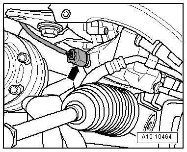
- Disconnect the connector - arrow - at servotronic solenoid valve (N119).
- Remove - A - (if equipped) from the steering gear (2 bolts).
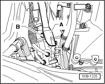
• Only remove universal joint from steering gear with front wheels in straight ahead position.
• Do not change steering wheel position and steering gear position.
- Remove bolt - B - for universal joint at steering gear and remove universal joint from steering gear.
Affects Vehicles with 3.0L TDI Engine
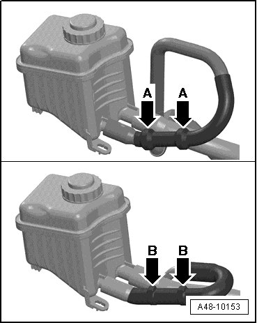
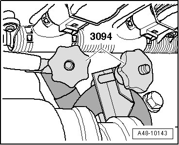
• The (3094) must not be secured on return hose in check valve area.
• The check valve is in the return hose between the cambers - A arrows - or between hose clamps - B arrows -.
Check Valve in Return Hose
- Clamp the intake hose and the return line on the reservoir using (3094).
- Remove bracket for hydraulic lines - 1 -.
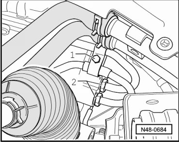
- Remove pressure line and return line - 2 - from steering gear.
Affects All Vehicles
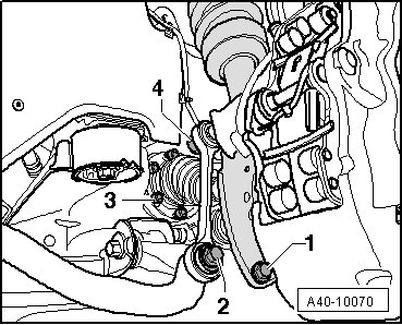
- Disconnect left and right connectors - 2 -.
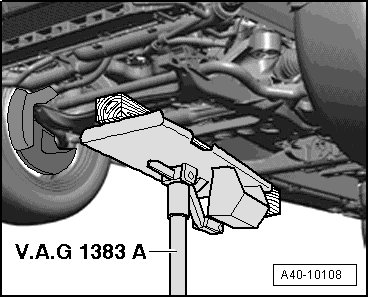
- Place (V.A.G 1383 A) with wooden block under subframe and press lightly against.
- Subframe, locating, refer to => [ Subframe, Securing ] Description and Operation.
- Remove bolts - 4 -.
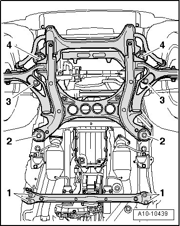
- Lower subframe approximately 200 mm with (V.A.G 1383 A).
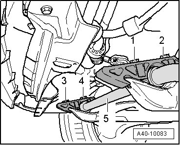
- Remove bolts - 1 - to - 4 -.
- Remove stabilizer bar - 5 -.
Pressing Off
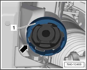
- Attach supporting ring (T10301/8) so that narrow side - arrow - faces subframe.
• Supporting ring (T10301/8) must be able to be attached easily and must not be canted.
- Install tools as shown in the illustration.
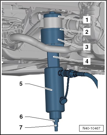
1. Thrust piece (T10301/5)
2. Support ring (T10301/8)
3. Tube (T10301/3)
4. Spacer (T10301/9)
5. Hydraulic cylinder (VAS 6178)
6. Nut (T10301/2)
7. Spindle (T10301/1)
- Press out the bonded rubber mount.
Hold the (VAS 6178) during the pressing-out procedure.
Installation Position
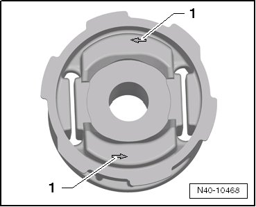
One of the arrows - 1 - must point in direction of travel
Pressing In the Bonded Rubber Mount
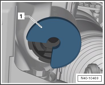
- Install the thrust plate (T10301/10) - 1 - with the open side to the subframe.
When pressing in bonded rubber bushing, make sure that (T10301/10) is in correct position to prevent subframe from damage.
- Mount the tools as illustrated.
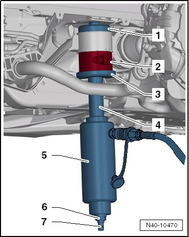
1. Thrust piece (T10301/7)
2. Bonded rubber mount
3. Thrust plate (T10301/10)
4. Spacer (T10301/11)
5. Hydraulic cylinder (VAS 6178)
6. Nut (T10301/2)
7. Spindle (T10301/1)
- Press in bonded rubber bushing until shoulder lies gap-free at subframe sleeve.
Replacing the front bonded rubber bushing in direction of travel, V8 TDI from MY 11
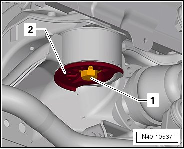
- Place the (V.A.G 1383 A) under the subframe.
- Remove the front subframe bolts - 1 - and the thrust washers - 2 -.
- Lower the subframe - 1 -.
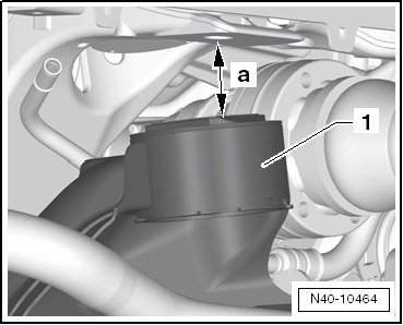
• a - maximum 40 mm
Pressing Off
- Attach the supporting ring (T10301/14) - 1 - so that the narrow side - arrow - faces the subframe.
• Supporting ring (T103301/14) must be able to be attached easily and must not be canted.
- Mount the tools as illustrated.
1. Thrust piece (T10301/5)
2. Support ring (T10301/14)
3. Tube (T10301/13)
4. Spacer (T10301/9)
5. Hydraulic press (VAS 6178) with pressure head (T10205/13)
6. Nut (T10301/2)
7. Spindle (T10301/1)
• Before pressing out, place the (V.A.G 1383 A) with the universal mount under the cylinder since the cylinder may fall down at the end of the pressing out procedure.
• Hold the hydraulic press (VAS 6178) during the pressing-out procedure.
- Press out the bonded rubber mount.
Installation Position
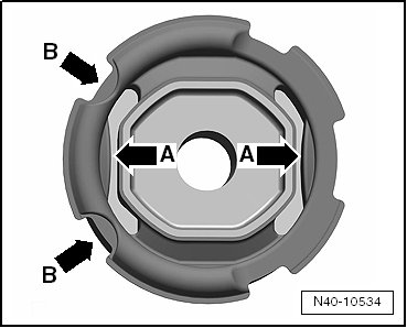
• The cams - arrows A - must point in the longitudinal vehicle direction.
• The cutouts - arrows B - must point in the direction of travel.
Pressing In the Bonded Rubber Mount
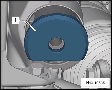
- Install the thrust plate (T10301/15) - 1 - with the open side to the subframe.
When pressing in the bonded rubber bushings, make sure that the thrust plate (T10301/15) is positioned correctly, to prevent the subframe from being damaged.
- Mount the tools as illustrated.
1. Thrust piece (T10301/7)
2. Bonded rubber mount
3. Thrust plate (T10301/15)
4. Spacer (T10301/11)
5. Hydraulic press (VAS 6178) with pressure head (T10205/13)
6. Nut (T10301/2)
7. Spindle (T10301/1)
- Press in bonded rubber bushing until shoulder lies gap-free at subframe sleeve.
Pressing Out the Bonded Rubber Mount
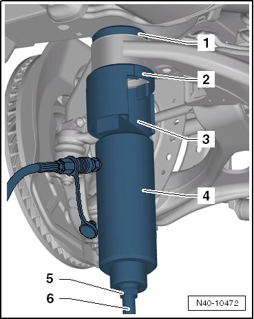
- Mount the tools as illustrated.
1. Thrust piece (T10301/5)
2. Support ring (T10301/8)
3. Tube (T10301/3)
4. Hydraulic cylinder (VAS 6178)
5. Nut (T10301/2)
6. Spindle (T10301/1)
- Press out the bonded rubber mount.
Hold the (VAS 6178) during the pressing-out procedure.
Installation Position
One of the arrows - 1 - must point in direction of travel
Pressing In the Bonded Rubber Mount
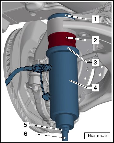
- Mount the tools as illustrated.
1. Thrust piece (T10301/7)
2. Bonded rubber mount
3. Thrust plate (T10301/6)
4. Hydraulic cylinder (VAS 6178)
5. Nut (T10301/2)
6. Spindle (T10301/1)
- Press in bonded rubber bushing until shoulder lies gap-free at subframe sleeve.
Installing
Installation is the reverse of removal, with special attention to the following:
Tightening specifications, refer to => [ Subframe, Stabilizer Bar and Coupling Rod Overview ] Front Axle Overview
Tightening specifications, refer to => [ Steering Gear Overview ] Steering Gear Overview
- Tighten the driveshaft.
- Tighten the wheels.
- On vehicles with air suspension, position vehicle on wheels. Refer to => [ Positioning Vehicle on Hoist and Wheels ] Positioning Vehicle on Hoist and Wheels.
- Bleed the steering system. Refer to=> [ Steering System, Bleeding after Reinstalling ] Service and Repair.
- Check power steering fluid level. Refer to => [ Power Steering, Checking Hydraulic Oil Level ] Power Steering, Checking Hydraulic Oil Level.
- Check the steering system for leaks. Refer to => [ Steering System, Checking for Leaks ] Steering System, Checking For Leaks.