Subframe, Stabilizer Bar, Transverse Link, Ball Joint and Vehicle Level Sensor Overview
Subframe, Stabilizer Bar, Transverse Link, Ball Joint and Vehicle Level Sensor Overview
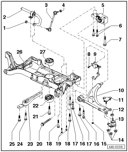
1 Nut
• 65 Nm
• Always replace if removed.
• Counter hold at socket head of joint bolt when tightening
2 Stabilizer Bar
• Removing and Installing, refer to => [ Stabilizer Bar ] Front Suspension
• Different versions, allocation, refer to the Parts Catalog
3 Coupling Rod
• Linking the stabilizer bar to the suspension strut
4 Nut
• 65 Nm
• Always replace if removed.
• Counter hold at socket head of joint bolt when tightening
5 Bracket
• Locating, refer to => [ Securing Mounting Bracket ] Description and Operation
• With bonded rubber bushing
• Transverse link mounting bracket, replacing => [ Transverse Link Mounting Bracket ] Transverse Link Mounting Bracket
6 Bolt
• 50 Nm + 90° turn
• Always replace if removed.
7 Bolt
• 70 Nm + 90° turn
• Always replace if removed.
8 Bolt
• 9 Nm
9 Left Front Level Control System Sensor (G78) and Right Front Level Control Sensor (G289)
• Removing and Installing, refer to => [ Level Control System Sensor ] Front Suspension
10 Transverse Link
• Transverse link with mounting bracket, removing and installing => [ Transverse Link With Mounting Bracket ] Transverse Link with Mounting Bracket
• Transverse link bonded rubber bushing, replacing => [ Transverse Link Bonded Rubber Bushing ] Service and Repair
• Transverse link mounting bracket, replacing => [ Transverse Link Mounting Bracket ] Transverse Link Mounting Bracket
11 Locking Element
• Always replace if removed.
12 Nut
• 20 Nm + 90° turn
• Always replace if removed.
13 Ball Joint
• Removing and Installing, refer to => [ Ball Joint ] Removal and Replacement
• Checking, refer to => [ Ball Joint, Checking ] Procedures
14 Nut
• 40 Nm + 45° turn
• Always replace if removed.
15 Nut
• 9 Nm
16 Bolt
• 70 Nm + 90° turn
• Always replace if removed.
• Positioned with the indentation on the bolt head at the rear bolting point on the underbody
• There are different versions depending on the country, allocation, refer to the Parts Catalog
• Note the different bolt lengths
17 Bolt
• 70 Nm + 90° turn
• Always replace if removed.
• There are different versions depending on the country, allocation, refer to the Parts Catalog
18 Bolt
• 50 Nm + 90° turn
• Always replace if removed.
• Threaded connection on steering gear
19 Bolt
• 20 Nm + 90° turn
• Threaded connection on stabilizer bar
• Always replace if removed.
20 Bolt
• 70 Nm + 180° turn
• Always replace if removed.
• Tighten only in curb weight position. Refer to => [ Wheel Bearing, Lifting To Curb Weight Position ] Front Suspension.
21 Bolt
• 100 Nm + 90° turn
• Always replace if removed.
• Tighten only when the pendulum support is bolted to the transmission
22 Lower Bonded Rubber Bushing for Pendulum Support
• Removing and Installing, refer to => [ Subframe Bonded Rubber Bushing ] Service and Repair
23 Pendulum Support
• Bolt first to transmission, then to subframe
• Different versions, allocation, refer to the Parts Catalog
24 Bolt
25 Bolt
26 Subframe
• Removing and Installing, refer to => [ Subframe ] Subframe
• Subframe, servicing => [ Subframe Bonded Rubber Bushing ] Service and Repair
• Subframe, securing => [ Subframe, Securing ] Description and Operation
• Different versions, allocation, refer to the Parts Catalog
27 Upper Bonded Rubber Bushing for Pendulum Support
• Removing and Installing, refer to => [ Subframe Bonded Rubber Bushing ] Service and Repair