Electronic Brake Control Module: Service and Repair
ABS Control Module and ABS Hydraulic Unit
Disconnecting ABS Control Module (J104) and ABS Hydraulic Unit (N55) is not permitted.
Special tools, testers and auxiliary items required
• Brake Pedal Actuator (V.A.G 1869/2)
• Vehicle Diagnosis, Testing and Information System (VAS 5051)
Removing
- Read the control module version and make a note of it.
- Disconnect the battery. Be sure to get the radio code beforehand.
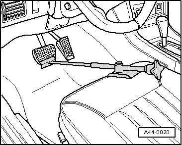
- Insert (V.A.G 1869/2) between brake pedal and driver's seat by pressing brake pedal down at least 60 mm.
- Connect bleeder bottle hose to left front and left rear brake caliper bleeder screw.
- Open left rear and left front brake caliper bleeder screws to reduce pressure in hydraulic unit.
- Close left front and rear brake caliper bleeder screws.
- Do not remove (V.A.G 1869/2).
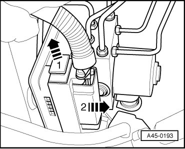
- Release control module harness connector - arrow 1 - and pull off - arrow 2 -.
• Make sure that no brake fluid enters control module connector housing. This could lead to corrosion of the contacts and thereby cause the system to fail.
• A contaminated housing must be carefully cleaned with compressed air.
- To protect against escaping brake fluid, place a lint-free rag in the area under the control module and hydraulic unit.
- Mark brake lines. Refer to => [ ABS Control Module and ABS Hydraulic Unit ABS/ESP Mark 60 Assembly Overview ] ABS Control Module and ABS Hydraulic Unit ABS/ESP Mark 60 Assembly Overview.
Do not bend or kink brake lines!
- Disconnect the tie up the brake lines on the hydraulic unit - 2 - leading to the master brake cylinder.
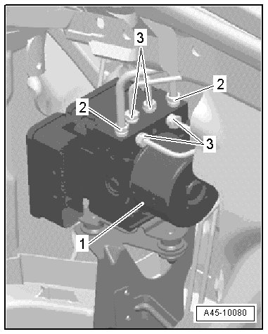
- Remove the remaining brake lines - 3 - from hydraulic unit.
• Disconnecting hydraulic pump - 1 - from hydraulic unit is not permitted.
- Seal brake lines and threaded holes with plugs from repair kit.
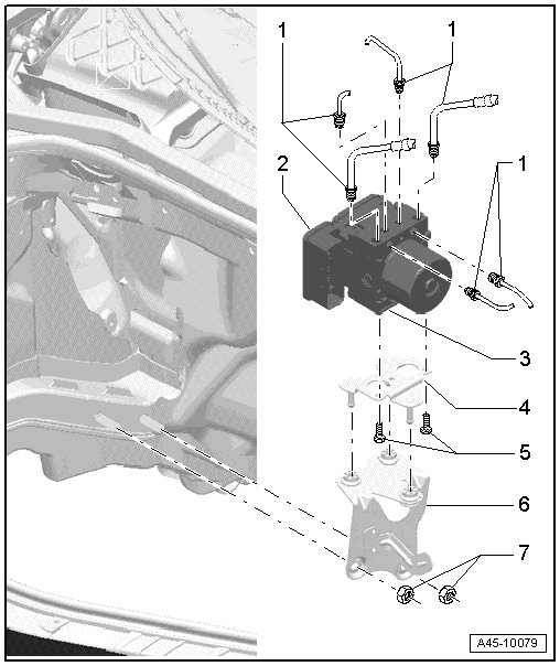
- Carefully remove the hydraulic unit - 2 - together with the control module and bracket - 4 - from the rubber buffers in the bracket - 6 -.
- Remove hydraulic unit from the vehicle.
- Remove the bolts - 5 - from the bracket - 4 - and remove the bracket.
Excessive shaking (e.g. dropping, impact) may destroy the control module. Control module must then no longer be used.
- Set hydraulic unit with control module down on a clean surface.
• After removing control module and hydraulic unit, seal threaded holes and brake lines with sealing plugs - 1H0.698.311.A.
The hydraulic pump must not be separated from the hydraulic unit.
Installing
Installation is the reverse of removal, with special attention to the following:
• For customer service, hydraulic unit is filled with brake fluid.
• If sealing plugs are removed before corresponding brake line is installed, brake fluid leaks out. If that is the case, sufficient brake system bleeding can no longer be ensured.
- Tighten the bolts - 5 - on the bracket - 4 - to 8 Nm.
- Carefully install the hydraulic unit - 2 - together with the control module and bracket - 4 - on the rubber buffers in the bracket - 6 -.
• Be careful not to press the rubber buffers through bracket when installing the unit.
- Connect brake lines according to marking.
If the brake line connections are interchanged, the ESP system will malfunction.
- Tighten brake lines on hydraulic unit.
- Connect the connector to the control module.
- Bleed the brake system. Refer to => [ Brake System Bleeding ] Brake System Bleeding.
- After securing brake lines to hydraulic unit, perform output diagnostic test mode.
• By performing the output check diagnosis, it can be determined if the line connections were interchanged.
• If ABS hydraulic unit was replaced, it must be coded.
• Use (VAS 5051) for this.
- On display, select:
• Chassis
• Brake system (Repair group 01;45)
• 01- On Board Diagnostic (OBD) capable systems
• 03- Brake electronics ABS/ESP Mark 60
- Select desired function on display:
• J104- ABS/ASR/ESP Control Module Mark 60
• J104- ABS/ASR/ESP Control Module, Functions
• J104- Control module, coding
The following sensors should also be calibrated after replacing control module:
• Steering Angle Sensor (G85)
• Sensor for transverse acceleration (G200)
• Brake Pressure Sensor 1 (G201)
• On AWD vehicles, longitudinal acceleration sensor (G251)
Use (VAS 5051) for this.
- On display, select:
• Chassis
• Brake System
• 01- On Board Diagnostic (OBD) capable systems
• 03- Brake electronics ABS/ESP Mark 60
- Select desired function on display:
• J104- ABS/ASR/ESP Control Module Mark 60
• J104- ABS/ASR/ESP Control Module, Functions
- Then perform the ESP driving and system tests.
Make sure the brakes are working correctly before driving the vehicle for the first time.