I.On-Car Serviceable Transaxle Components
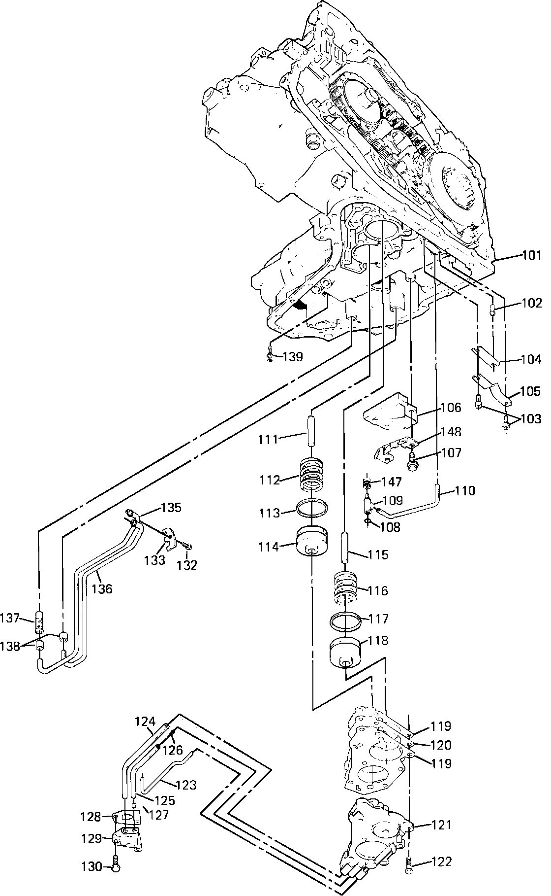
The following list of the parts illustrated in Figures 1 and 2 can be serviced on-car (attaching screws, bolts, and conical washers are not listed). The part reference number, following the part name, is the same number found in Figures 1 and 2 of this bulletin, as well as the Service Information Manual (SIM) Sections 7A and 440-T4 and the GMWDD Parts Illustrations. Those items with an asterisk (*) have revised service procedures outlined in Section III of this bulletin, which are different from those originally published in the SIM. These items with an asterisk (*) will be included in the next SIM revision (May, 1985). If repairs require removal of the channel plate (Figure 1, part #24), the unit must be exchanged.
FIGURE 1 - CASE SIDE COVER PARTS REFERENCE:
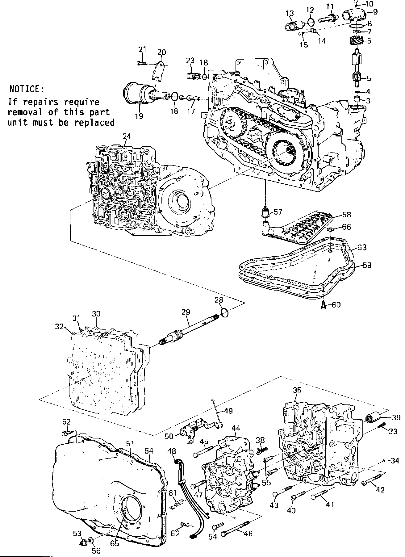
FIGURE 2 - BOTTOM OIL PAN PARTS REFERENCE:
Figures 1, 2 and Section 440-T4 Parts
Modulator........................................... #19
Modulator O-Ring.................................... #18
Modulator Retainer.................................. #20
Modulator Bolt...................................... #21
Modulator Valve .................................... #17
Governor Cover....................................... #9
Governor Cover O-Ring ............................... #8
Governor Thrust Bearing ............................. #7
Speedo Drive Gear ................................... #6
Governor Assembly.................................... #5
*Side Cover ......................................... #51
*Side Cover Gasket................................... #64
*Side Cover/Channel Plate ............................#65
*Oil Pump Assembly................................... #44
(and related sub-assemblies)
*T.V. Lever and Bracket Assembly..................... #50
*T.V. Link........................................... #49
Servo Pipe Retainer ............................... #133
*Control Valve Assembly ..............................#35
Alignment Sleeve .................................. #406
*Detent Spring and Roller Assembly ................. #707
*TCC Wiring Harness.................................. #61
*Clips (harness)............................... #62 & #67
*Case Connector...................................... #23
*Case Connector O-Ring............................... #18
*Solenoid Assembly.................................. #328
*Solenoid O-Ring ................................... #329
*Spacer Plate........................................ #31
*Spacer Plate Gasket C/P ............................ #30
*Spacer Plate Gasket S.P./V.B........................ #32
*Oil Pump Drive Shaft ............................... #29
*O.P. Drive Shaft O-Ring ............................ #28
Magnet .................................................#66
Trans. Oil Pan ........................................ #59
Trans. Oil Pan Gasket.................................. #63
Filter Assembly........................................ #58
Governor Oil Pipe Retainer............................ #129
Governor Retainer Gasket.............................. #128
Governor Feed Screen ................................. #126
Governor Feed Pipe ................................... #125
Governor Return Pipe.................................. #124
Lube Pipe - Final Drive............................... #123
Accumulator Cover..................................... #121
Accumulator Cover Gaskets . ..... .................... #119
Accumulator Cover Spacer Plate ....................... #120
Accumulator Pins ............................... #111 & 115
1-2 Accumulator Spring................................ #116
1-2 Accumulator Piston................................ #118
3-4 Accumulator Spring................................ #112
3-4 Accumulator Piston................................ #114
Accumulator Piston Seals ...................... #113 & #117
Drive Sprocket Support Lube Pipe ..................... #110
Lube Pipe Retainer.................................... #109
Lube Pipe Retainer O-Ring............................. #108
Oil Scoop ............................................ #106
1-2 Servo Bracket .................................... #148
Cooler Connectors ......... ................... #526 & #569
Thermo Element .................................. #102-#105
Axle Oil Seals ................................ #405 & #540
Vent Assembly......................................... #528
Pipe Plug ............................................ #529
In addition to those parts illustrated in Figures 1 and 2, the following list of parts illustrated in Section 7A of the 1985 SIM are also serviceable.
Section 7A - Parts
Transaxle Filler Tube................................ #13
Transaxle Filler Tube Seal........................... #14
TV Cable............................................. #16
TV Cable Seal ....................................... #17
Speed Sensor ........................................ #29
Speed Sensor Seal ................................... #30
Speedo Driven Gear .................................. #31
Reverse Servo .................................... #87-96
(and related sub-assemblies).................. & 107
Cooler Lines and/or Fittings .................... #108-111
Auxiliary Oil Cooler ................................ #190
Shift Control Cable.................................... #1
Transaxle Mounts.......................... #112-116 & 118-
(and related sub-assemblies) ........... 119, 122-123
Pressure Switches 3rd............................................. #148
4th............................................. #147
*Transaxle Assembly ................................. #121