A/T - Delayed/Harsh/Erratic Shifting
Bulletin No. T 85-53File In Group 7
Number 117
Date Feb. '85
SUBJECT: SHIFT CONDITIONS - THM 440-T4 TRANSAXLE
MODELS AFFECTED: 1985 FWD DEVILLES AND FLEETWOODS
Some early production 1985 FWD Deville and Fleetwood vehicles equipped with HT4100 engines and THM 440-T4 "AY" transaxles may exhibit any or all of the following shift conditions:
1. Harsh 3-2 downshift at 25-35 MPH.
2. Harsh 4-2 downshift at 45-55 MPH.
3. Shift "busyness" (4-3-4 shift pattern) at highway speeds.
4. Delayed/harsh 1-2 and 2-3 upshifts at lower vehicle speeds.
5. Engine braking effect during a 2-1 manual downshift at 25-30 MPH.
It should be noted that the procedure outfined in this bulletin applies exclusively to Cadillac vehicles equipped with model "AY" transaxles.
FIGURE 1 - Transmission I.D. Nameplate:
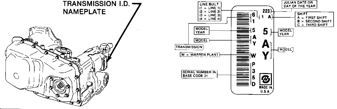
To assist the five listed shift conditions on THM 440-T4 model "AY" transaxles with a Julian build date of 223 or lower (refer to Figure 1), install control valve assembly calibration-update kit, service package P/N 8646936, with gasket kits P/N 8646907 and 8644902, using the following service procedure:
1. Verify correct operation of the vacuum modulator and TV system. Refer to diagnosis and repair procedures in Section 7A and 440-T4 of the 1985 FWD Deville and Fleetwood Service Information Manual (SIM) as well as Serviceman Bulletin T-85-9, Group 7, #112. If the condition is not repaired after following these published service procedures, go to Step 2 of this procedure.
2. Remove the control valve assembly as outlined on page 7A-26 of the 1985 FWD Deville and Fleetwood SIM. The following notes will assist during removal of the control valve assembly:
a. Prior to performing step 9 of the SIM procedure, remove the left engine splash shield which will provide more access to the pan bolts and the control valve assembly. Also, disconnect the vacuum pump from the cradle. Support the vacuum pump assembly to prevent any possible wiring and vacuum hose damage.
FIGURE 2 - Left Cradle Member:
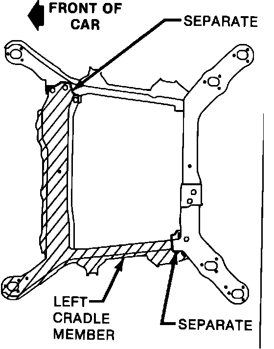
b. At step 9, remove the left cradle member (refer to Figure 2 for points of separation).
FIGURE 3 - Mount Location:
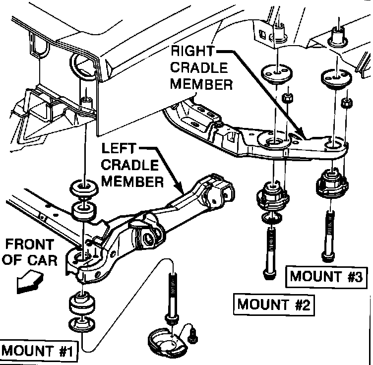
c. Prior to performing step 10, the right cradle mounts #2 and #3 need to be removed to allow increased transaxle lowering (refer to Figure 3).
FIGURE 4 - Support Fixture:
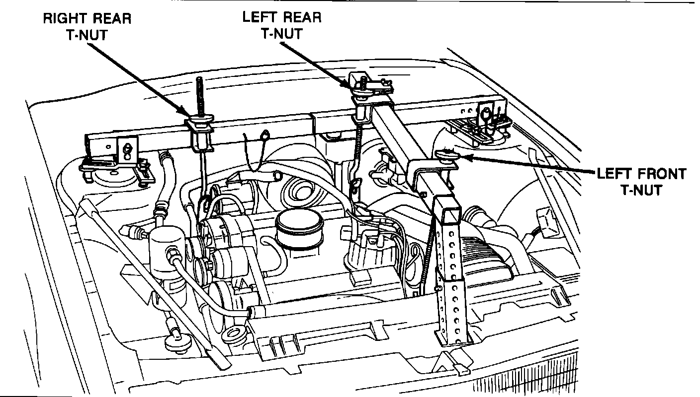
d. At step 10, in order to obtain maximum clearance for side pan removal, the engine and transaxle assembly needs to be tilted downward at the left front and raised at the left rear. This is accomplished by positioning the driver's side rear support rod of the Engine Support Fixture (J-28467) until it extends approximately six inches above the T-nut and the driver's side front support rod is lowered until the top of the support rod is flush with the top of the T-nut (refer to Figure 4).
NOTICE: The Service Information Manual will be revised in May of 1985 to include these notes.
FIGURE 5 - Control Valve Assembly:
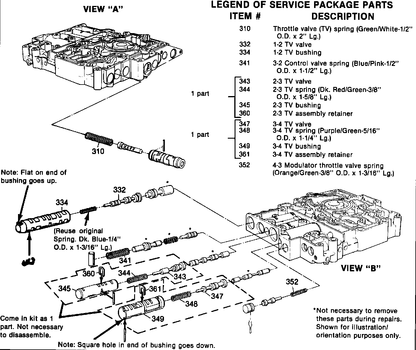
3. Install the parts contained in service package P/N8646936 into the control valve assembly (refer to Figure 5). This package contains one each of the following parts:
^ 1-2 TV valve and bushing* (Items #332 and 334)*
^ 2-3 TV bushing assembly** (Items #343, 344, 345 and 360)
^ 3-4 TV bushing assembly** (Items #347, 348, 349 and 361)
^ Throttle valve (TV) spring (Item #310)
^ 3-2 control valve spring (Item #341)
^ 4-3 modulator throttle valve spring (Item #352)
(*Reuse original 1-2 TV spring with new valve and bushing from kit.) (**Assembly consists of the bushing, valve, spring and assembly retainer clip.)
FIGURE 6 - Check Ball Locations - Channel Plate And Control Valve Assembly:
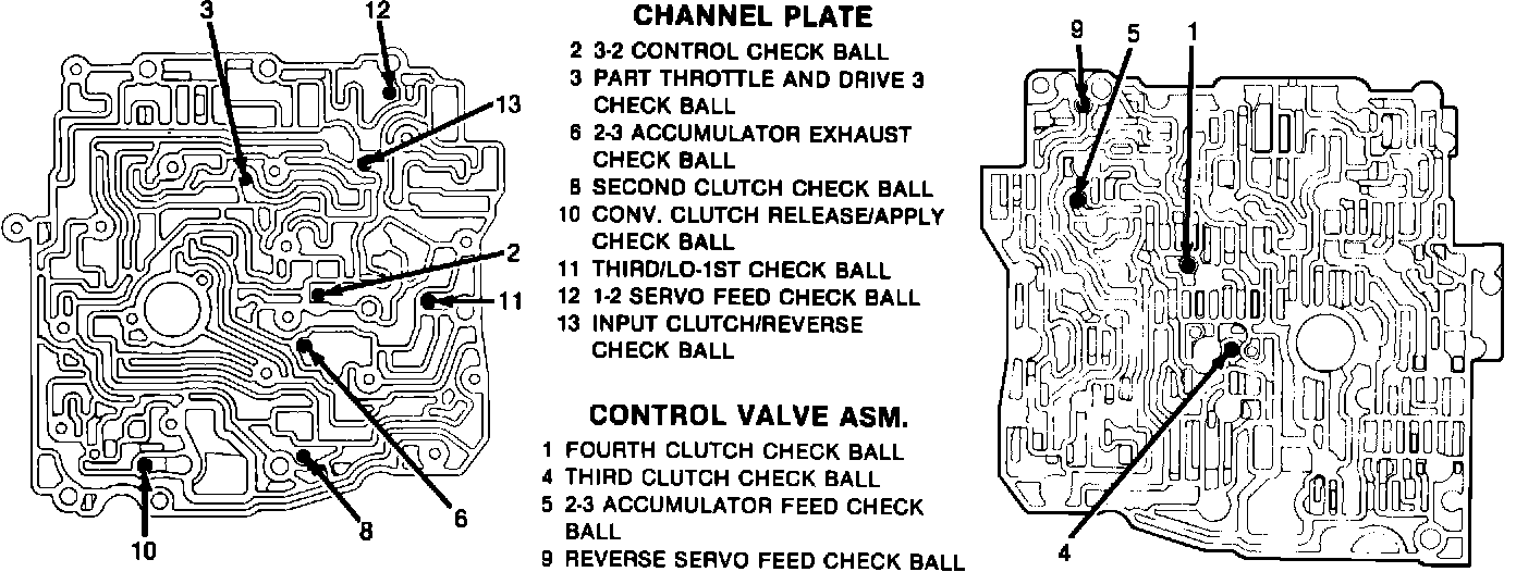
4. Install the overhauled control valve assembly onto the transaxle with new inner and outer spacer plate gaskets (both are in kit P/N 8646907) as outlined on page 7A-26 of the SIM. Refer to Figure 6 for the correct location of the check balls. Install the side cover with new gaskets (both are in kit P/N 8644902). Retain the check balls and gaskets in place with petroleum jelly only.
For warranty purposes, use labor Operation No. T6111 at 3.3 hours for R&R and overhaul of the control valve assembly.