Improper Blower Speed
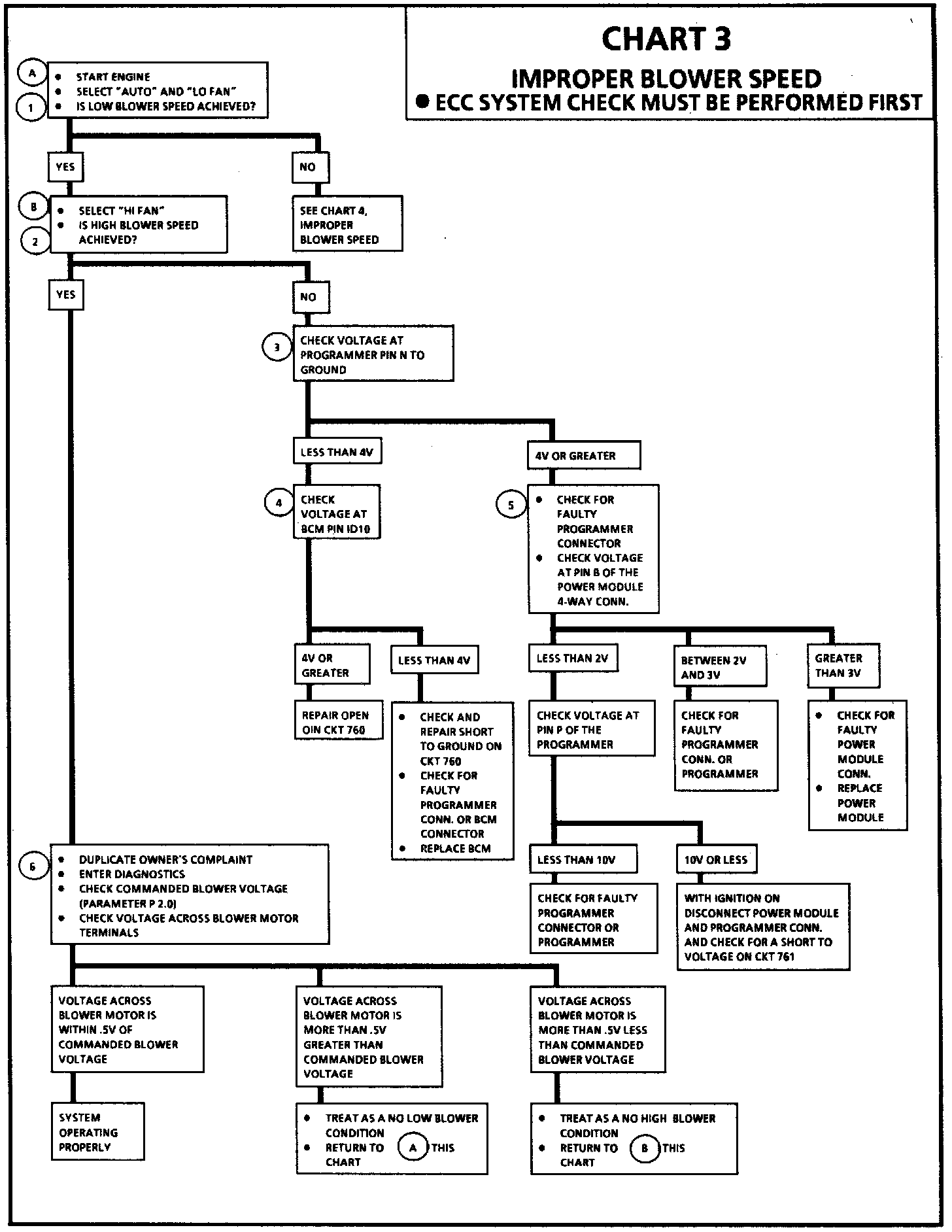
Chart 3:
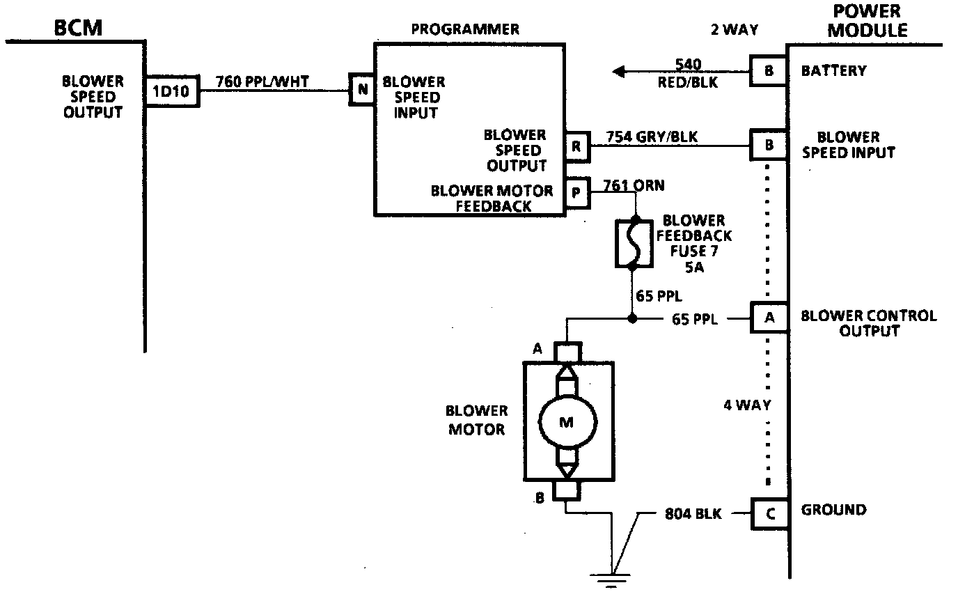
Electrical Schematic:
CIRCUIT DESCRIPTION
Based on a signal sent from the Body Control Module (BCM), the programmer sends a variable voltage to the power module which is then amplified and sent to the blower motor. The programmer monitors the blower voltage so that the signal can be adjusted to achieve the desired blower motor speed.
TEST DESCRIPTION
Numbers below refer to circled numbers on the diagnostic chart:
1. Checks for low fan operation.
2. Checks for high fan operation.
3. Checks the commanded blower speed input to the programmer.
4. Checks the commanded blower speed signal out of the BCM.
5. Checks the blower speed control input to the power module.
6. Checks the accuracy of variable blower speed control.