ABS/TC - Revised Diagnostic Table For DTC 67
File In Section: 05 - BrakesBulletin No.: 01-05-25-003
Date: March 2001
SERVICE MANUAL UPDATE
Subject:
Revised ABS/TC Diagnostic Table for DTC 67 Requested Engine Torque Circuit Malfunction
Models:
1997 Cadillac Catera
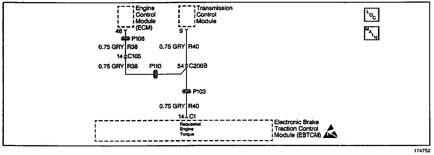
This bulletin is being issued to revise the Diagnostic Routines for DTC 67. This additional information is being added to conditions for setting the DTC and in the Diagnostic Table Step 2. The technician is directed to check for DTCs stored in the ECM. The knock sensor DTCs P0325 and P0330 will set in the ECM and cause DTC 67 to set in the EBTCM if a torque reduction is requested. This condition will not turn on the Service Engine Soon (SES) indicator until a second knock sensor failure. Therefore, the technician will not realize to check the ECM for DTCs when diagnosing the EBTCM DTC 67. Please use the following to replace the existing information in the ABS/Traction Control sub-section of the Service Manual.
This information has been updated within SI 2000. If you are using a paper version of this Service Manual, please mark a reference to this bulletin on the affected page in the ABS/Traction Control sub-section of the Service Manual.
Circuit Description
The traction control system uses the ECM fuel and the ignition controls to limit the drive wheel slippage during acceleration. The ECM reduces engine torque by retarding spark timing, and/or shutting off up to three injectors. The EBTCM sends a torque request to the ECM via a Pulse Width Modulated (PWM) signal requesting the desired torque level for proper traction control system operation. The ECM then provides a delivered torque PWM signal informing the EBTCM how much actual torque is produced by the engine.
Conditions for Setting the DTC
^ If a defective requested torque signal is detected by the ECM, a PWM signal outside the normal range is sent to the EBTCM via the delivered torque circuit. The DTC will set if the EBTCM receives the Out of range signal 3 consecutive times.
^ The ECM can not carry out a requested torque reduction when a knock sensor DTC is set. When the knock sensor DTC is set, the ECM sends the EBTCM an invalid PWM signal which will set an ECM and EBTCM DTC and disable the TCS.
^ There is an open in the circuit.
^ There is a short to ground.
^ There is a short to voltage.
^ The EBTCM must detect an engine RPM greater than 480 RPM to set the DTC.
Action Taken When the DTC Sets
^ A malfunction DTC is stored.
^ The TC indicator lamp is turned on.
^ The SES indicator lamp is turned on when the knock sensor fails a second consecutive drive trip that the diagnostic runs and fails.
^ The TCS is disabled.
^ The ABS remains functional.
Conditions for Clearing the DTC
^ The condition for the DTC is no longer present.
^ The scan tool Clear DTCs function is used.
^ 100 drive cycles have passed with no DTCs detected.
Diagnostic Aids
The following can cause an intermittent malfunction:
^ A poor connection can cause an intermittent malfunction.
^ Rubbed through wire insulation can cause an intermittent malfunction.
^ A wire that is broken inside the insulation can cause an intermittent malfunction.
Check for the following in any circuit suspected of causing an intermittent malfunction:
^ Check for backed out terminals.
^ Check for improper mating.
^ Check for broken locks.
^ Check for improperly formed terminals.
^ Check for damaged terminals.
^ Check for poor terminal to wiring connections.
^ Check for physical damage to the wiring harness. Perform a thorough inspection of the wiring. Perform a thorough inspection of the connectors. Failure to carefully and fully inspect the wiring and the connectors may result in misdiagnosis. Misdiagnosis causes part replacement with reappearance of the malfunction.
Test Description
The number(s) below refer to the step number(s) on the diagnostic table as shown.
2. This verifies that a knock sensor DTC is present.
3. It is very important to check ground G103. Corrosion or a loose connection at this point may cause a malfunction in the PWM signal.
4. The scan tool can be used to check the requested engine torque signal from the EBTCM. The reading should remain steady when TCS is inactive. The reading will fluctuate between 2% and 10% if observed when TCS is active.
5. This test checks the presence of a pull-up voltage from the EBTCM.
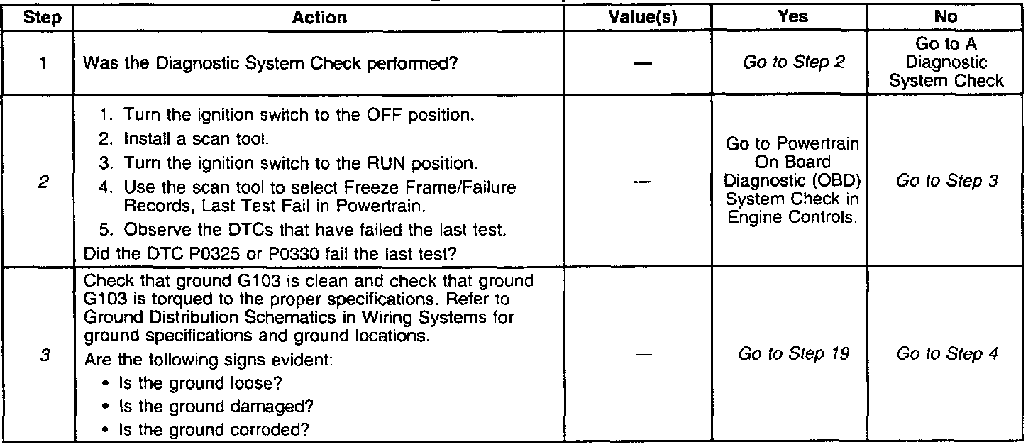
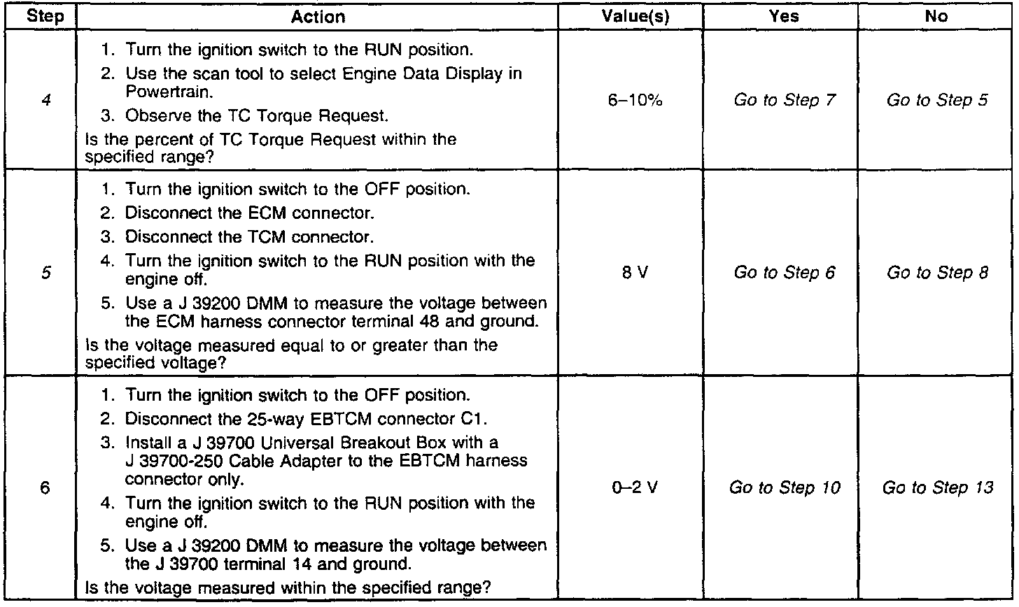
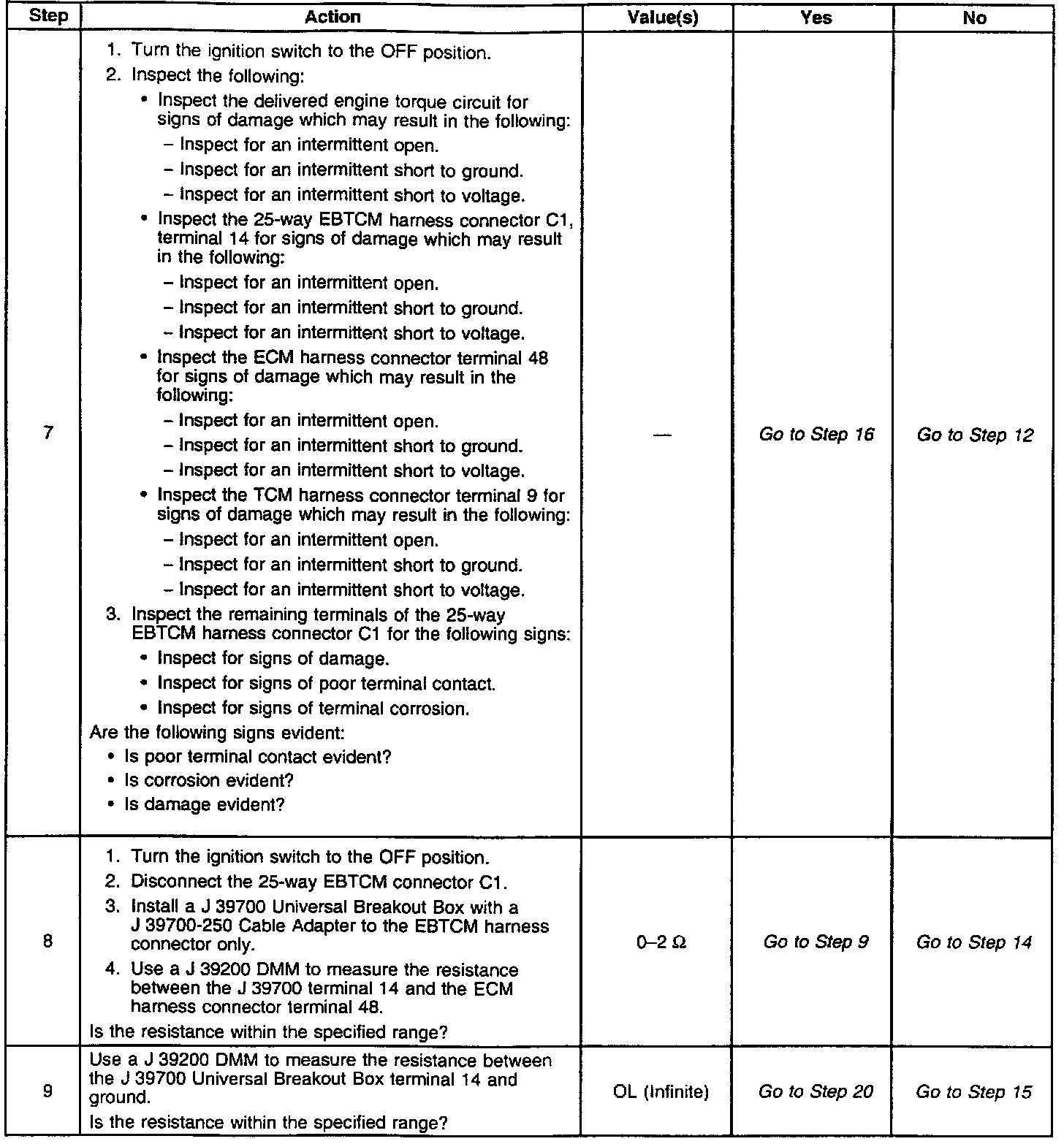
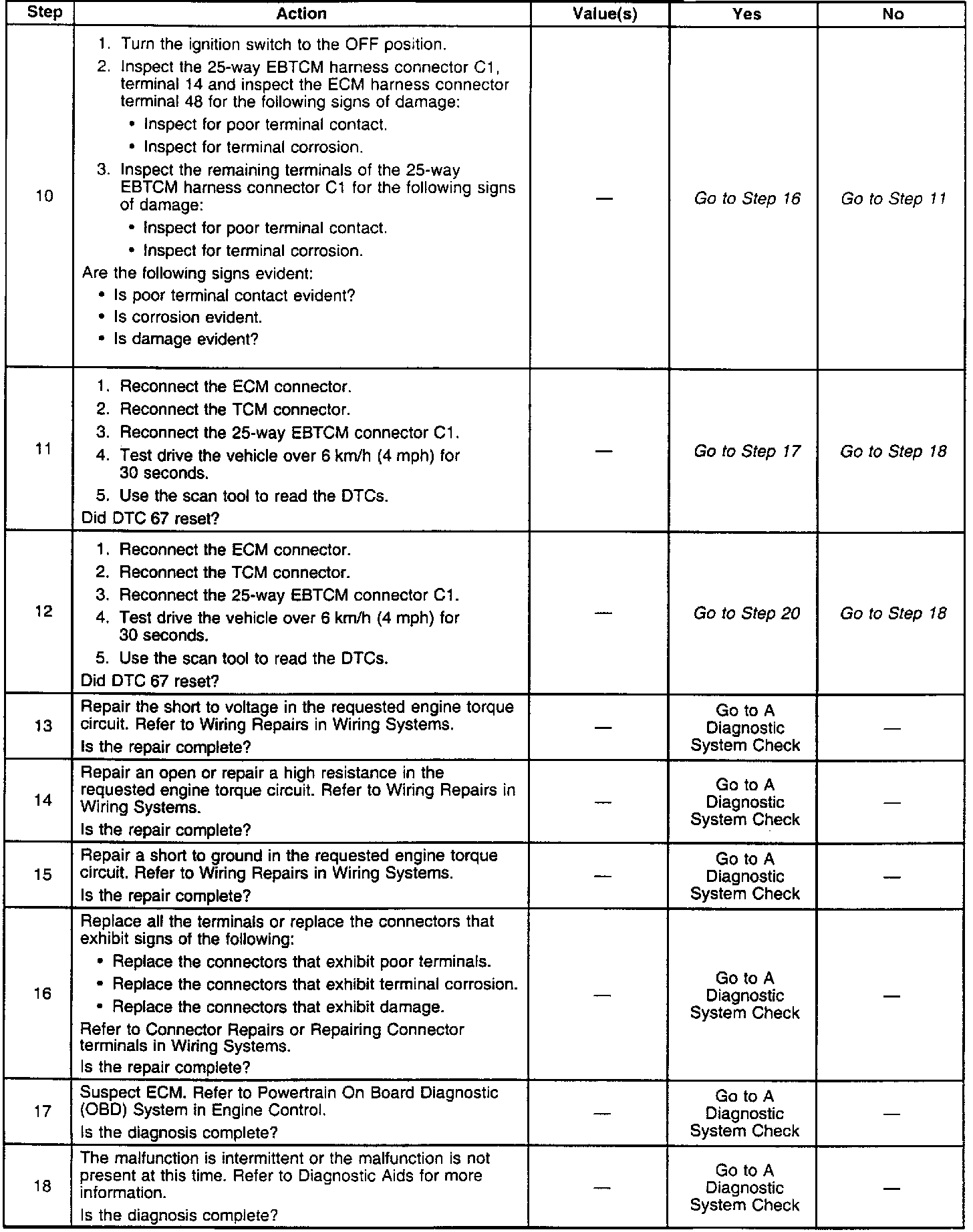

DTC 67 - Requested Engine Torque Circuit Malfunction

DISCLAIMER