Water Crossover Replacement
Removal Procedure
^ Tools Required
- J38185 Hose Clamp Pliers
1. Drain the cooling system. Refer to Draining and Filling Cooling System.
2. Remove the air cleaner assembly.
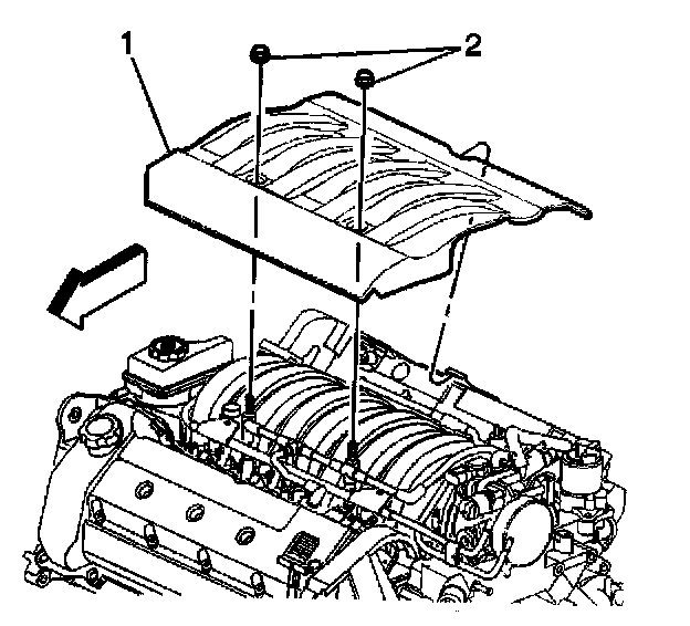
3. Remove the two nuts (2) from the intake manifold sight shield (1).
4. Remove the sight shield (1) from the engine.
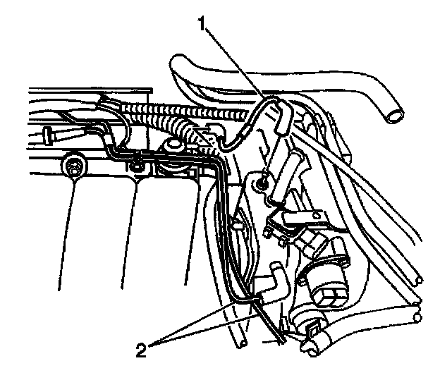
5. Disconnect the brake booster vacuum tube from the water housing crossover.
6. Disconnect the fuel regulator vacuum tube (1).
7. Disconnect the AIR solenoid vacuum tube (2).
8. Remove the throttle body.
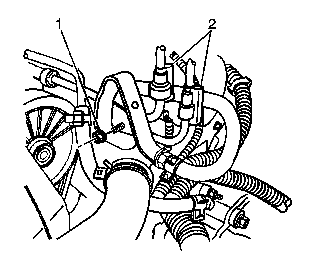
9. Disconnect the fuel rail bracket retaining nut (1) at the rear lift bracket.
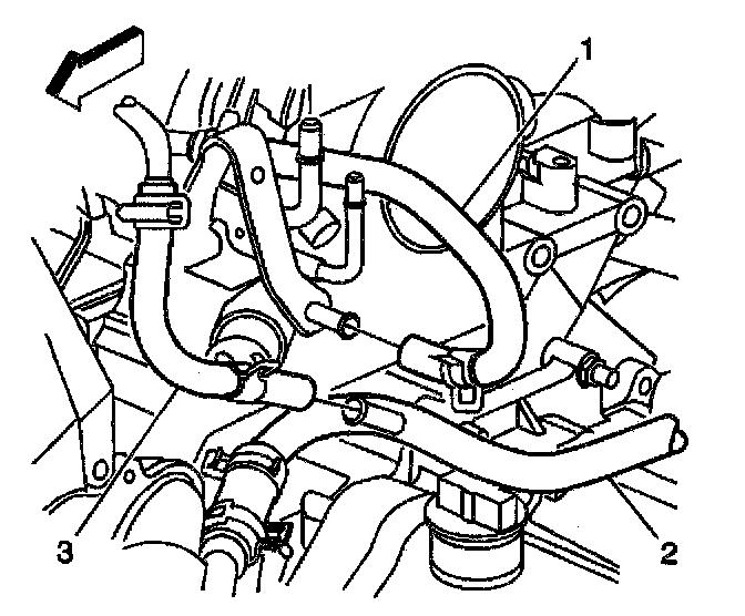
10. Disconnect the surge tank inlet hose (1) from the fitting.
11. Disconnect the generator coolant hose (3) from the heater pipe (2).
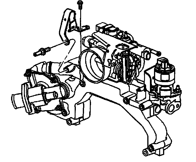
12. Remove the surge tank inlet fitting.
13. Remove the rear lift bracket bolt.
14. Remove the rear lift bracket.
15. Remove the EGR valve.
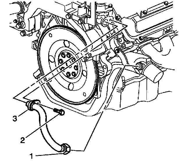
16. Disconnect the EGR inlet pipe nut (1) from the exhaust crossover.
Important: The EGR valve inlet pipe incorporates a crush seal connection at the water crossover. The EGR valve inlet pipe must be replaced if disconnected from the water crossover.
17. Remove the EGR inlet pipe bolt (2) and flange (3) from the water crossover.
18. Remove the EGR inlet pipe and discard.
19. Remove the EVAP emission canister purge valve.
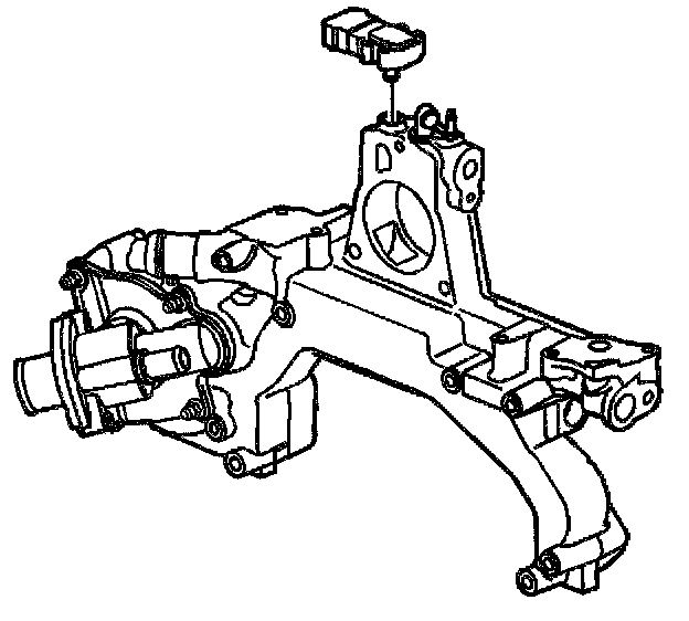
20. Disconnect the electrical connector from the MAP sensor.
21. Remove the MAP sensor.
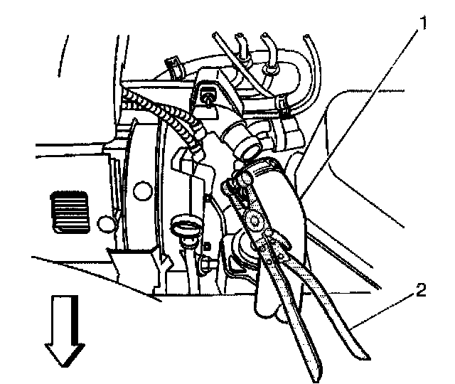
22. Position the J38185 (2) to the clamp in order to remove the inlet radiator hose (1) from the water housing crossover.
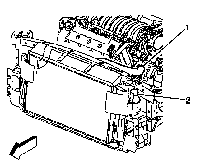
23. Position the J38185 to the damp in order to remove the outlet radiator hose (2) from the thermostat housing.
24. Remove the water pump.
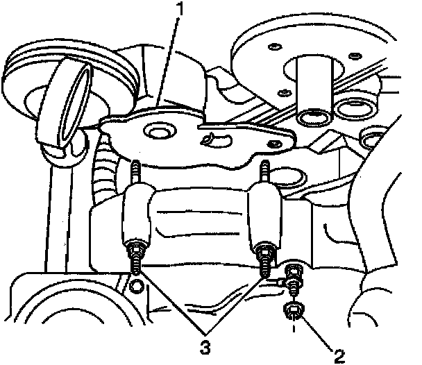
25. Remove the two bolts (3) attaching the water pump belt tensioner (1) to the water crossover.
26. Remove the water pump belt tensioner (1).
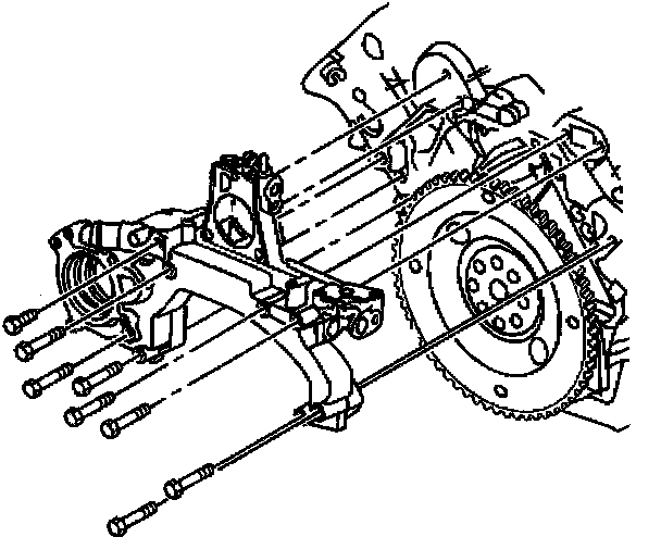
27. Disconnect the cable harness clip at the water housing crossover and position aside.
28. Disconnect the heater hose from the water housing crossover.
29. Remove the water housing crossover from the engine.
30. Clean and inspect the water housing crossover.
Installation Procedure
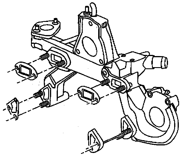
1. With all eight crossover retaining bolts inserted, slide the upper and lower water housing crossover gaskets onto the bolts.
Important: Care should be taken when installing the water housing bolts, so that the gaskets are in the correct position.
2. Place the water housing crossover in position and hand start the bolts to hold the crossover in place.
Notice: Refer to Fastener Notice in Service Precautions.
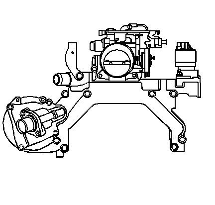
3. Tighten the water housing crossover bolts in sequence.
Tighten the bolts to 25 Nm (18 lb ft).
4. Connect the heater hose to the water housing crossover.
5. Connect the cable harness clip to the water housing crossover.
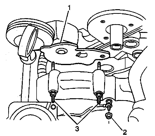
6. Install the two bolts (3) attaching the water pump belt tensioner (1) to-the water crossover.
Tighten the two bolts (3) to 10 Nm (89 lb in).
7. Install the water pump. Refer to Water Pump Replacement.
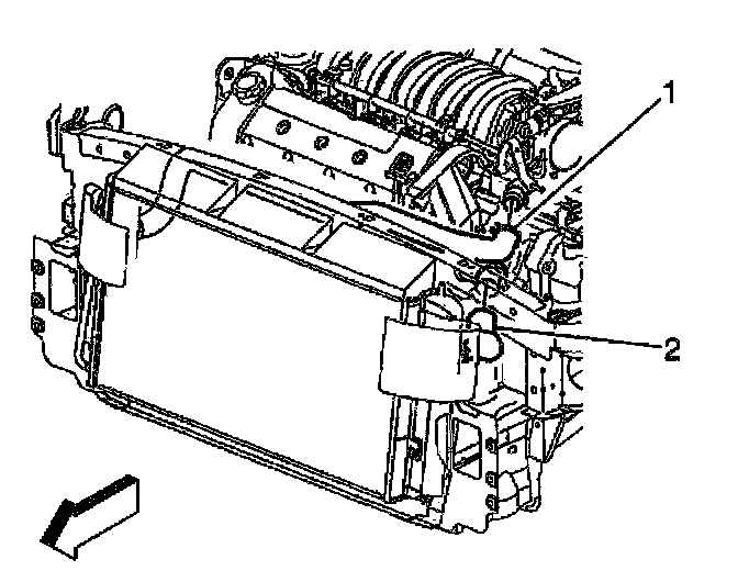
8. Position the J38185 to the clamp in order to connect the outlet radiator hose (2) to the thermostat housing.
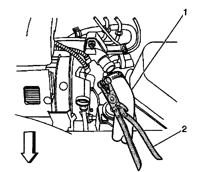
9. Position the J38185 (2) to the clamp in order to connect the inlet radiator hose (1) to the water housing crossover.
10. Install the MAP sensor.
11. Connect the electrical connector to the MAP sensor.
12. Install the EGR valve.
Important: The EGR valve inlet pipe incorporates a crush seal connection at the water crossover. The EGR valve inlet pipe must be replaced if disconnected from the water crossover.
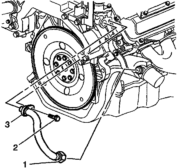
13. Hand start the NEW EGR inlet pipe-to-crossover pipe nut (1) to prevent crossthreading.
Tighten the EGR inlet pipe nut to 60 Nm (44 lb ft).
14. Connect the EGR inlet pipe flange (3) to the water crossover.
15. Install the EGR inlet pipe-to-water crossover flange bolt (2).
Tighten the EGR inlet pipe bolt to 25 Nm (18 lb ft).
16. Install the EVAP emission canister purge valve.
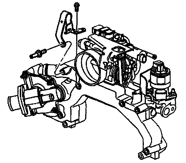
17. Position the rear lift bracket to the water crossover.
18. Install the rear lift bracket bolt.
Tighten the bolt to 24 Nm (18 lb ft).
19. Install the surge tank inlet fitting.
Tighten the fitting to 47 Nm (35 lb ft).
20. Connect the surge tank inlet hose (1) to the fitting.
21. Connect the generator coolant hose (3) to the heater pipe (2).
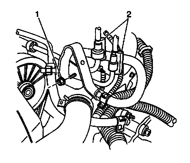
22. Connect the fuel rail bracket retaining nut (1) to the rear lift bracket.
Tighten the nut to 4 Nm (35 lb in).
23. Connect the AIR solenoid vacuum tube (2) to the housing crossover.
24. Connect the fuel regulator vacuum tube (1).
25. Connect the brake booster vacuum tube.
26. Install the throttle body.
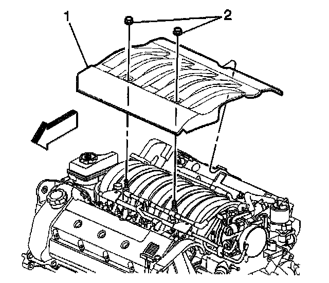
27. Position the intake mani1bid sight shield (1) to the engine.
28. Install the two intake manifold sight shield nuts (2).
Tighten the nuts to 3 Nm (27 lb in).
29. Install the air cleaner assembly.
30. Fill the cooling system. Refer to Draining and Filling Cooling System.