Ignition Switch
Ignition Switch Replacement
^ Tools Required
- J 42759 Ignition Switch Connector Release Tool
Removal Procedure
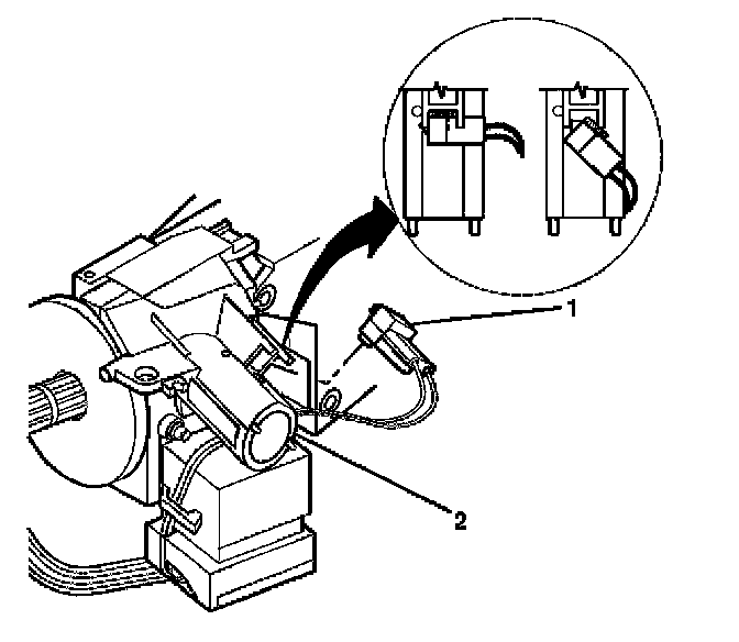
1. Caution: Refer to SIR Caution in Service Precautions.
Disable the SIR system.
2. Remove the theft deterrent control module. Refer to Theft Deterrent Control Module Replacement in Theft Deterrent.
3. Rotate the key alarm connector (1) 90 degrees.
4. Gently pull the key alarm connector (1) out of the ignition lock cylinder case assembly (2).
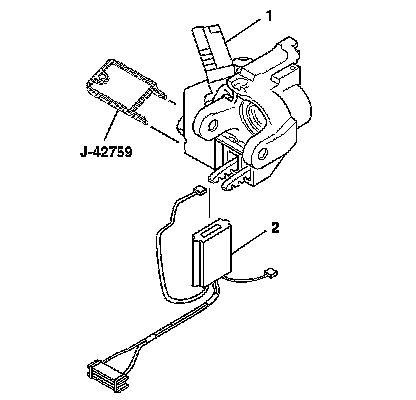
5. Disconnect the connector from the ignition switch assembly.
6. Remove the wires encased in the ignition switch clip (located on the side of the ignition switch).
7. Remove the ignition switch assembly (2) using J 42759.
Installation Procedure
1. Insert J 42759 into the ignition lock cylinder case assembly (1) and slide the ignition switch assembly (2) in.
2. Connect the connector to the ignition switch assembly (2).
3. Caution: Refer to SIR Inflator Module Coil Caution in Service Precautions.
Push the key alarm connector (1) into the ignition lock cylinder case assembly (2).
4. Rotate the key alarm connector (1) 90 degrees so that the key alarm connector (1) locks into place.
5. Install the wires back into the ignition switch clip.
6. Install the theft deterrent control module. Refer to Theft Deterrent Control Module Replacement in Theft Deterrent.
7. Enable the SIR system. Refer to SIR Disabling and Enabling Zone 3 in Restraint Systems.