Transmission Fluid Cooler Upper Pipe Assembly Replacement
Transmission Fluid Cooler Upper Pipe Assembly Replacement
Removal Procedure
1. Recover the refrigerant from the A/C system. Refer to Refrigerant Recovery and Recharging (Refrigerant Recovery and Recharging) .
2. Raise and support the vehicle. Refer to Lifting and Jacking the Vehicle (Service and Repair) .
3. Remove the wheelhouse panel. Refer to Wheelhouse Panel Replacement - Left Side (Service and Repair) .
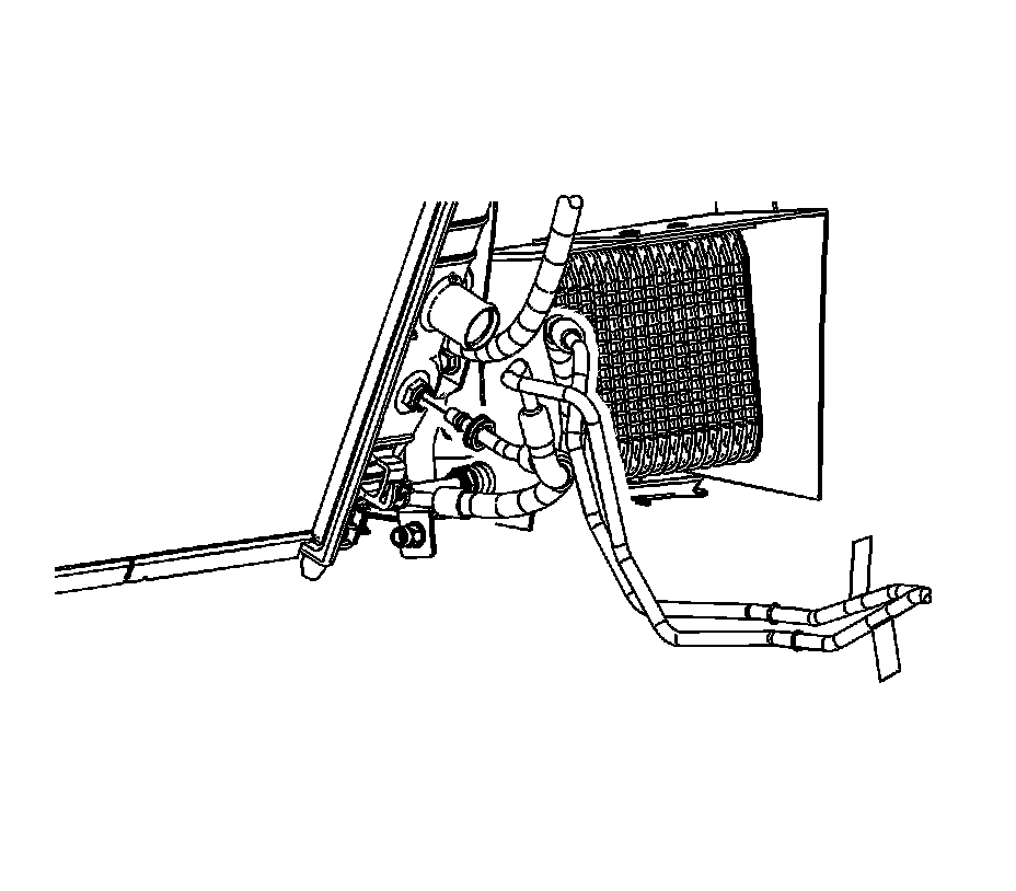
4. Disconnect the lower transmission oil cooler (TOC) line from the radiator. Refer to Transmission Fluid Cooler Hose/Pipe Quick-Connect Fitting Disconnection and Connection (Service and Repair) .
5. Remove the lower TOC line from the radiator. Refer to Transmission Fluid Cooler Hose/Pipe Quick-Connect Fitting Disconnection and Connection (Service and Repair) .
6. Remove the A/C compressor. Refer to Compressor Replacement (Service and Repair) .
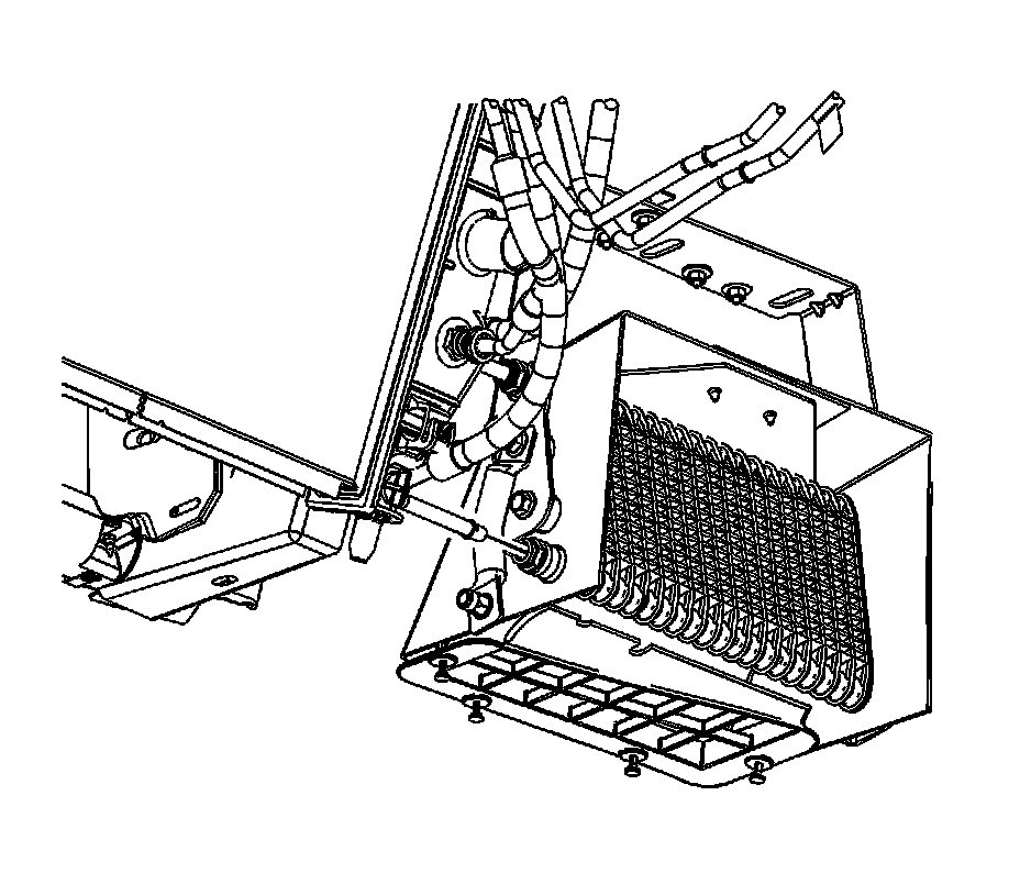
7. Disconnect the lower TOC line from the auxiliary TOC. Refer to Transmission Fluid Cooler Hose/Pipe Quick-Connect Fitting Disconnection and Connection (Service and Repair) .
8. Remove the lower TOC line from the auxiliary TOC. Refer to Transmission Fluid Cooler Hose/Pipe Quick-Connect Fitting Disconnection and Connection (Service and Repair)
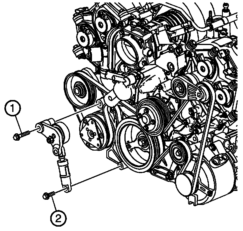
9. Remove the accessory belt tensioner top bolt (1).
10. Remove the accessory belt tensioner lower bolt (2).
11. Remove the accessory belt tensioner.
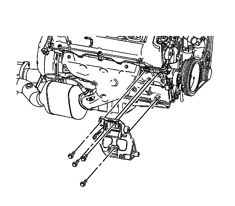
12. Remove the A/C compressor and power steering pump bracket bolts.
13. Remove the A/C compressor and power steering pump bracket.
14. Raise the engine cradle back into position.
Important: It is not necessary to fully tighten the cradle nuts to specification at this time. They will be removed again at a later step. Tighten until the cradle mounting nuts contacts the engine cradle.
15. Install the RH cradle mounting nuts.
16. Remove the support jacks from beneath the vehicle.
17. Lower the vehicle.
18. Install the engine support fixture. Refer to Engine Support Fixture (Engine Support Fixture) .
19. Raise the vehicle approximately 0.61 mm (2.0 ft) off the ground.
20. Support the engine cradle with a jack stands.
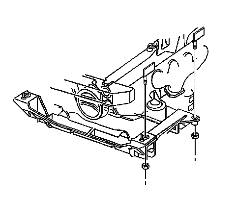
21. Remove the RH cradle mounting nuts.
22. Lower the RH engine cradle assembly approximately 51.0 mm (0.375 in)
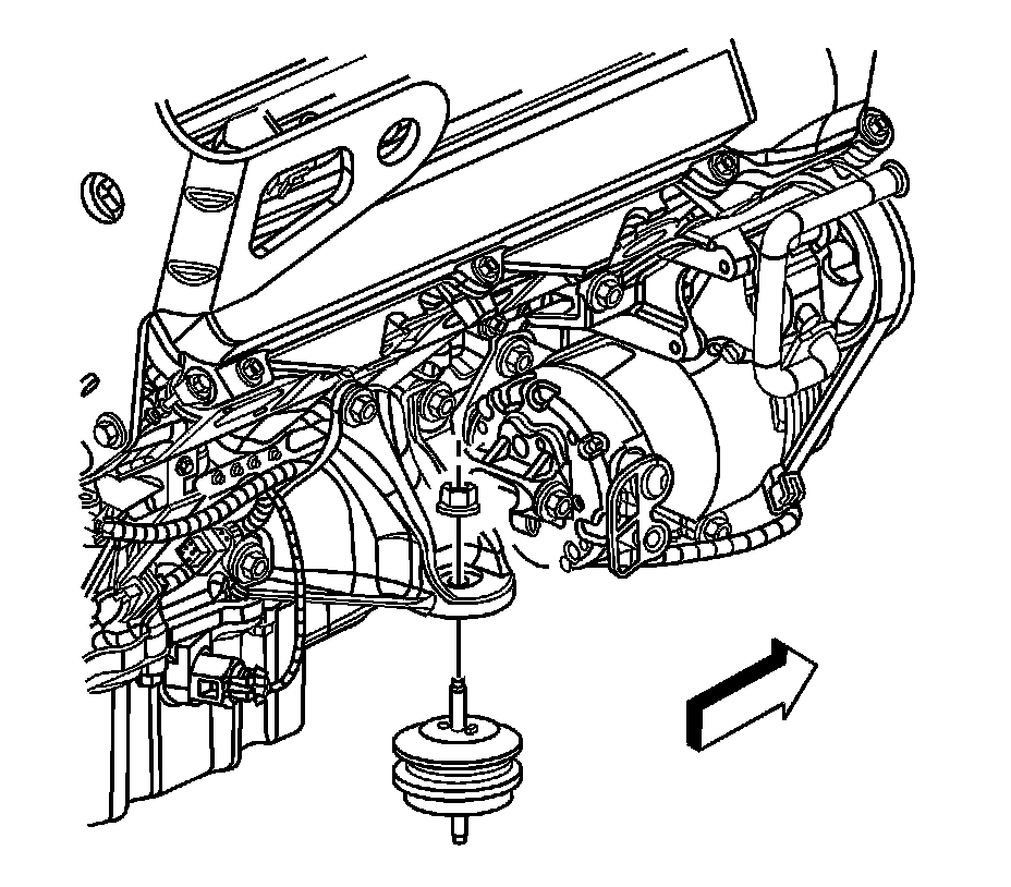
23. Remove the RH engine mount upper nut.
24. Remove the RH engine mount lower nut
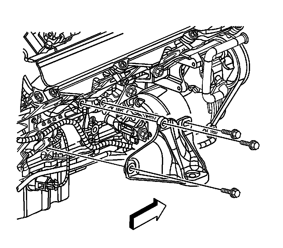
25. Remove the RH engine mount bracket bolts.
Important: It is necessary to elevate the engine assembly slightly to allow clearance for the RH engine mount bracket removal.
26. Using the J 28467-B , raise the engine assembly approximately 19.0 mm (0.75 in) to remove RH engine mount bracket
27. Remove the RH engine mount bracket.
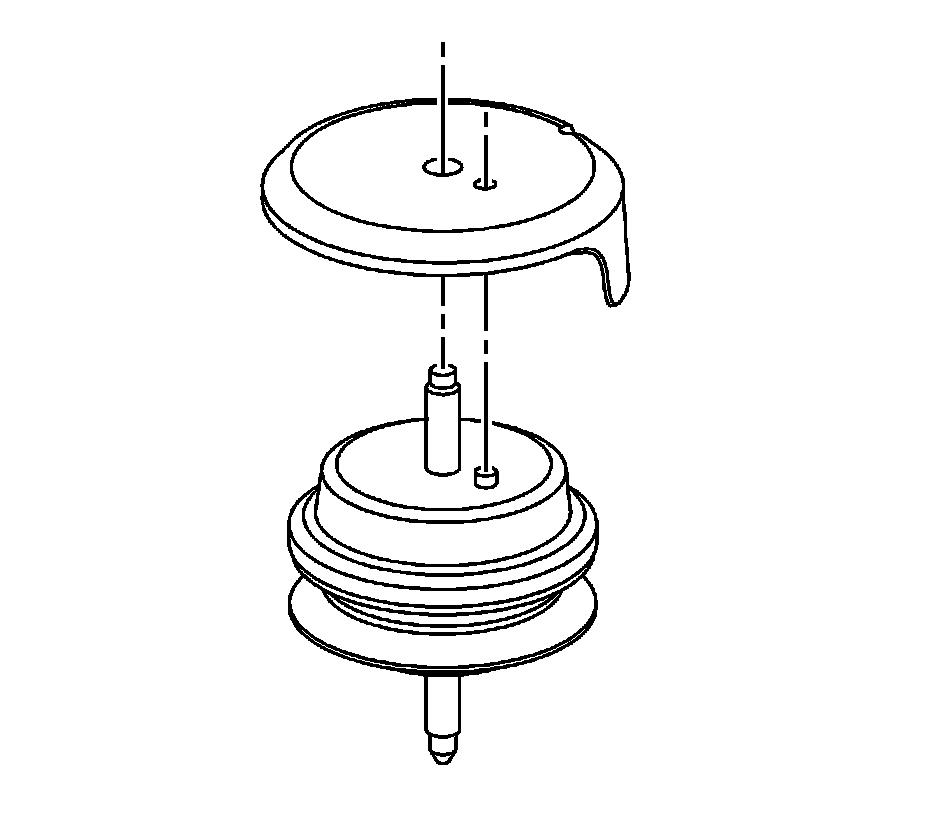
28. Remove the RH engine mount heat shield from the engine mount.
29. Remove the RH engine mount.
30. Raise and support the vehicle.
31. Remove the TOC line to oil pan retaining nuts.
32. Remove the TOC line to oil pan retaining clips.
33. Disconnect the upper and lower TOC retainer clip.
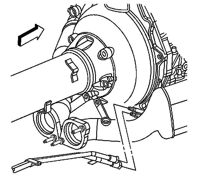
34. Disconnect the front TOC lines from the rear TOC line set.
35. Disconnect the oil level sensor electrical connector.
Important: Note the position of the TOC lines to ensure proper installation.
36. Remove the TOC lines. Refer to Transmission Fluid Cooler Hose/Pipe Quick-Connect Fitting Disconnection and Connection (Service and Repair) .
Installation Procedure
1. Install the TOC lines. Refer to Transmission Fluid Cooler Hose/Pipe Quick-Connect Fitting Disconnection and Connection (Service and Repair) .
2. Connect the oil level sensor electrical connector.
3. Connect the front TOC lines to the rear TOC line set.
4. Connect the upper and lower TOC retainer clip.
5. Install the TOC line to oil pan retaining clips.
Notice: Refer to Fastener Notice (Fastener Notice) .
6. Install the TOC line to oil pan retaining nuts.
Tighten the nuts to 12 N.m (9 lb ft).
7. Lower the vehicle.
Important: When installing the engine mount, be sure to have the locating dowel in the correct position.
8. Install the RH engine mount.
9. Install the RH engine mount heat shield to the engine mount.
10. Install the RH engine mount bracket.
11. Install the RH engine mount bracket bolts.
Tighten the bolts to 58 N.m (43 lb ft).
12. Using the J 28467-B , lower the engine assembly into position.
13. Install the RH engine mount lower nut
Tighten the nut to 58 N.m (43 lb ft).
14. Install the RH engine mount upper nut.
Tighten the nut to 58 N.m (43 lb ft).
15. Install the A/C compressor and power steering pump bracket.
16. Install the A/C compressor and power steering pump bracket bolts.
Tighten the bolts to 50 N.m (37 lb ft).
17. Install the accessory belt tensioner.
18. Install the accessory belt tensioner top bolt (1).
Important: Tighten in sequence.
Tighten the bolt to 25 N.m (18 lb ft).
19. Install the accessory belt tensioner lower bolt (2).
Tighten the bolt to 25 N.m (18 lb ft).
20. Install the A/C compressor. Refer to Compressor Replacement (Service and Repair) .
21. Install the lower TOC line to the auxiliary TOC. Refer to Transmission Fluid Cooler Hose/Pipe Quick-Connect Fitting Disconnection and Connection (Service and Repair) .
22. Connect the lower TOC line to the auxiliary TOC.
23. Install the lower TOC line to the radiator. Refer to Transmission Fluid Cooler Hose/Pipe Quick-Connect Fitting Disconnection and Connection (Service and Repair) .
24. Connect the lower TOC line to the radiator.
25. Install the wheelhouse panel. Refer to Wheelhouse Panel Replacement - Left Side (Service and Repair) .
26. Lower the vehicle.
27. Evacuate and recharge the A/C system. Refer to Refrigerant Recovery and Recharging (Refrigerant Recovery and Recharging) .
28. Check the transmission fluid level, add if necessary. Refer to Transmission Fluid Fill Procedure (Procedures) .