Cruise Control - Loss of Speed From Set Point or Hills
Number: 83-118Section: 9 (VIm)
Date: Jan., 1984
Subject: CRUISE CONTROL PERFORMANCE ON VEHICLES WITH THM 700-R4 TRANSMISSIONS
Model and Year: 1982-83 IMPALAS AND CAPRICES
TO: ALL CHEVROLET DEALERS
Some cruise control systems on 1982-83 Impalas and Caprices equipped with the THM 700-R4 transmission may experience a loss of speed from the set point on long hills. This condition may be due to certain vacuum conditions and may not allow a 4-3 downshift in the transmission.
Figure 1:
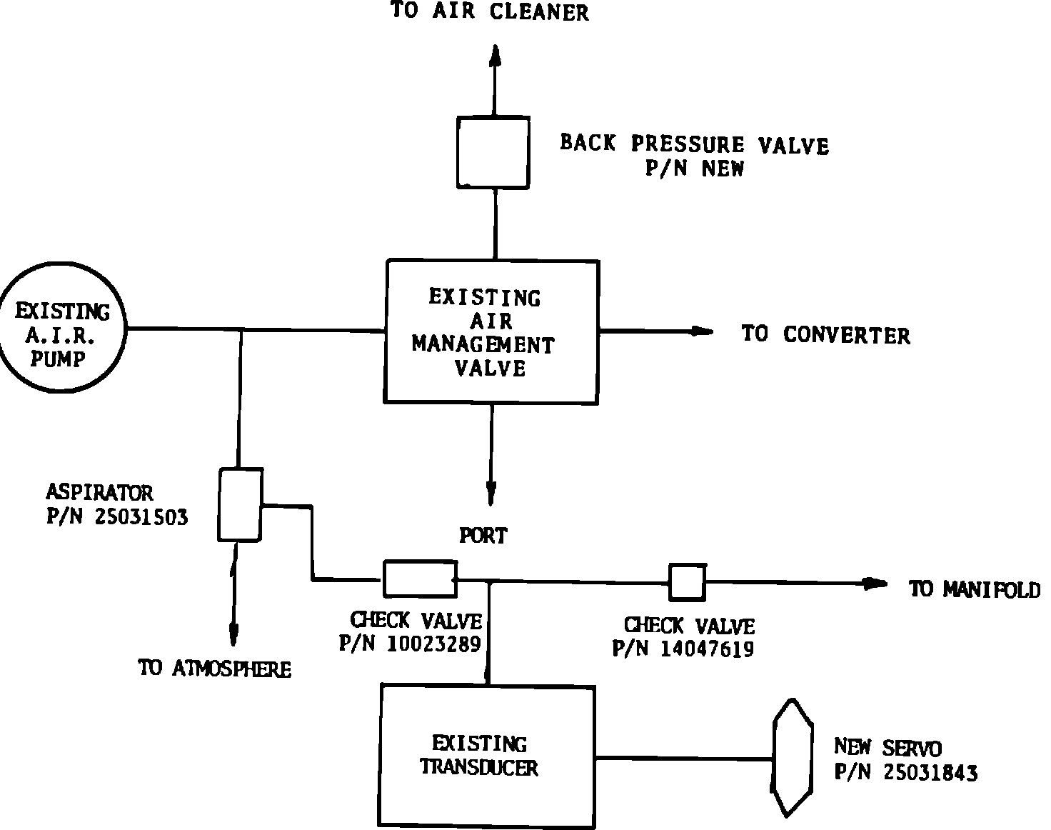
Service kit (P/N 14080393) has been released to correct this condition. The following instructions are included in the kit and should be used to correct the vehicle (reference Figure 1 for a diagram of the revised system).
Figure 2 - ASPIRATOR & BACK PRESSURE VALVE:
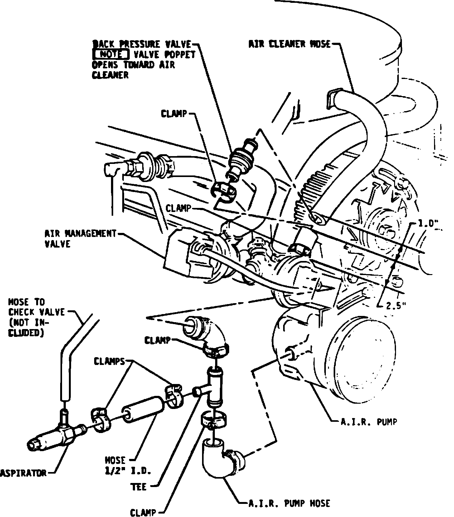
1. Cut hose between air management valve and air cleaner 2.5 inches from valve and remove 1 inch of hose from remainder and discard. Insert back pressure valve (P/N 14080391), poppet opening toward air cleaner, and clamp both ends of 2.5 inch hose with hose clamps (P/N 549589). See Figure 2.
2. Remove 3/4 inch of hose from between air management valve and air pump, discard. Insert tee (P/N 14080392) and clamp both ends with hose clamps (P/N 549589). Insert 2 inches 1/2 ID hose on third leg of tee. Insert aspirator (P/N 25031503) on other end of 2 inch hose. Clamp both ends of 2 inch hose with hose clamp (PIN 477402). See Figure 2.
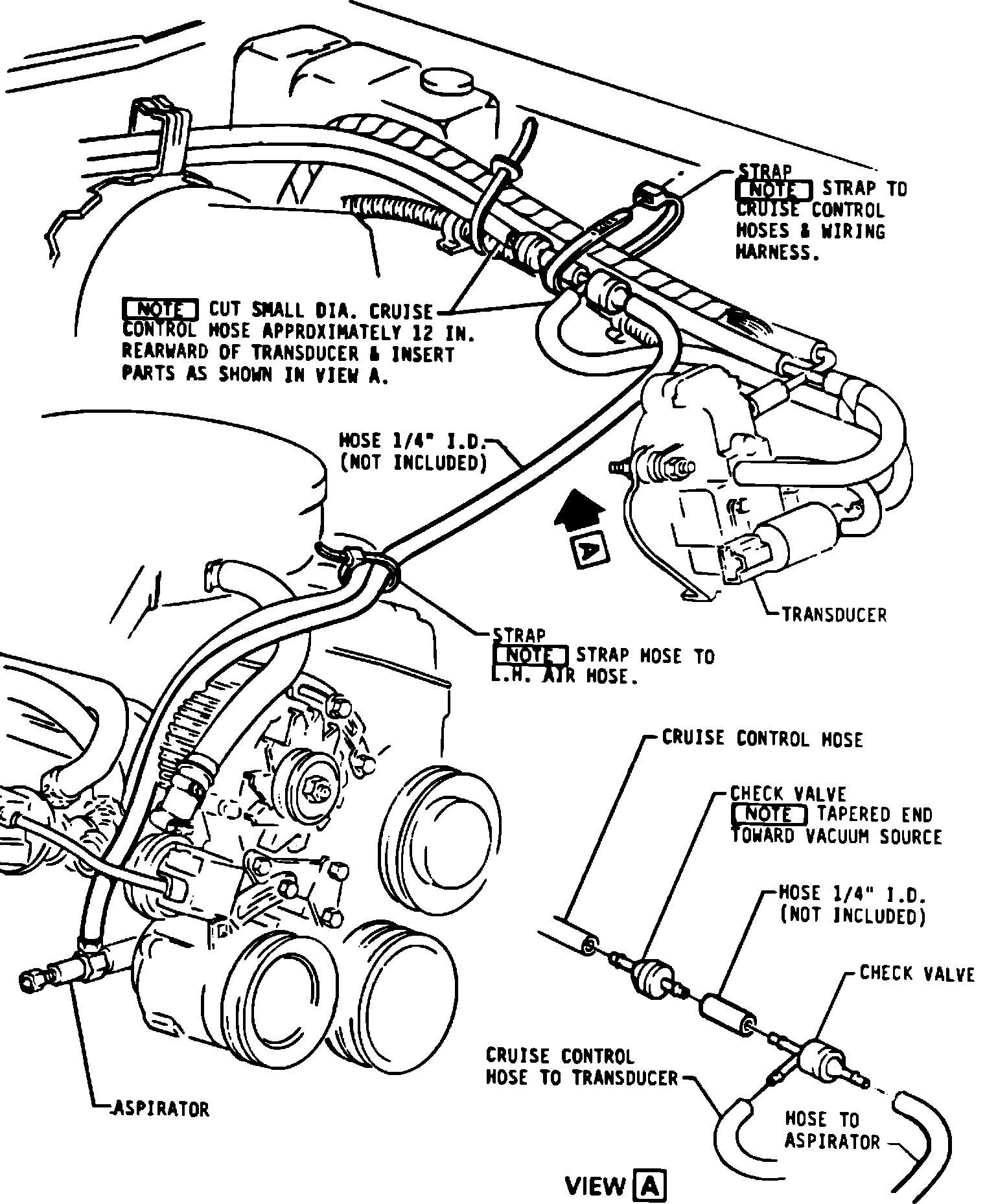
Figure 3 - ASPIRATOR HOSE TO CHECK VALVE:
3. Install new servo (P/N 25031843) in existing servo bracket with existing screws.
4. Cut vacuum hose from manifold to transducer 12 inches back from transducer. Insert check valve (P/N 14047619), 3 inches of 1/4 inch ID hose not included, and check valve (P/N 10023289) as shown in view A on Figure 3.
5. Insert other outlet of dual outlet side of P/N 10023289 into cut hose running to transducer. See Figure 3.
6. Add approximately 4 feet of 1/4 ID hose (not included) from aspirator (P/N 25031503) to single outlet side of P/N 10023289. See Figure 3.
7. Route above hose per drawing and band with straps (P/N 11501907) as shown.
PARTS LIST OF KIT (P/N 14080393)
Part Number Name Similar To Quantity
14080391 (New) Back Pressure Industrial 1
Valve Strainer Co.
#11330
549589 Hose Clamp 4
477402 Hose Clamp 2
14080392 (New) Tee Baylock #112795 1
25031503 Aspirator 1
10023289 Check valve 1
14047619 Check Valve 1
11501907 Strap - Plastic
Adjustable Tie 2
25031843 Servo 1
Tube*
Hose**
*Tube 5.16 - 5.96 ID, 10.06 - 10.82 OD (GM 6148-M (UMC 74381)). Approximately 4 feet not included.
**Hose 1/2 ID GM 6165M not included.
Labor Operation Number: T-1103
Labor Time : .4 hours