Torque Converter Clutch: Testing and Inspection
Fig. 006 - Wiring Diagram for Chart C-8A Transmission Converter Clutch. VIN Z:
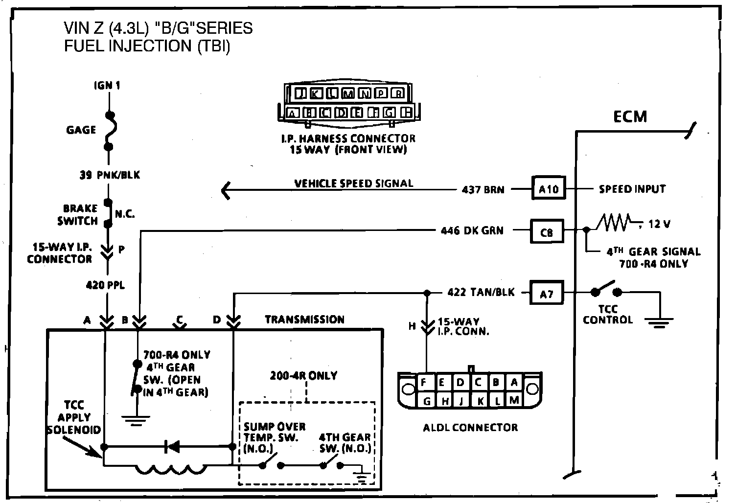
CHART C-8A
TRANSMISSION CONVERTER CLUTCH (TCC)
ELECTRICAL DIAGNOSIS
(Page 1 of 2)
4.3L "B/G" SERIES
FUEL INJECTION (TBI)
Circuit Description: The purpose of the automatic transmission torque converter clutch is to eliminate the power loss of the torque converter, when the vehicle is in a cruise condition. This allows the convenience of the automatic transmission and the fuel economy of a The purpose of the automatic transmission torque converter clutch is to eliminate the power loss of the torque converter, when the vehicle is in a cruise condition. This allows the convenience of the automatic transmission and the fuel economy of a manual transmission.
Fused battery ignition is supplied to the TCC solenoid through the brake switch. The ECM will engage TCC by grounding CKT 422 to energize the solenoid.
TCC will engage when:
- Vehicle speed above 24 mph
- Engine at normal operating temperature (above 70°C, 156°F)
- Throttle position sensor output not changing, indicating a steady road speed
- Brake switch closed
Fig. 005 Chart C-8A Transmission Converter Clutch:
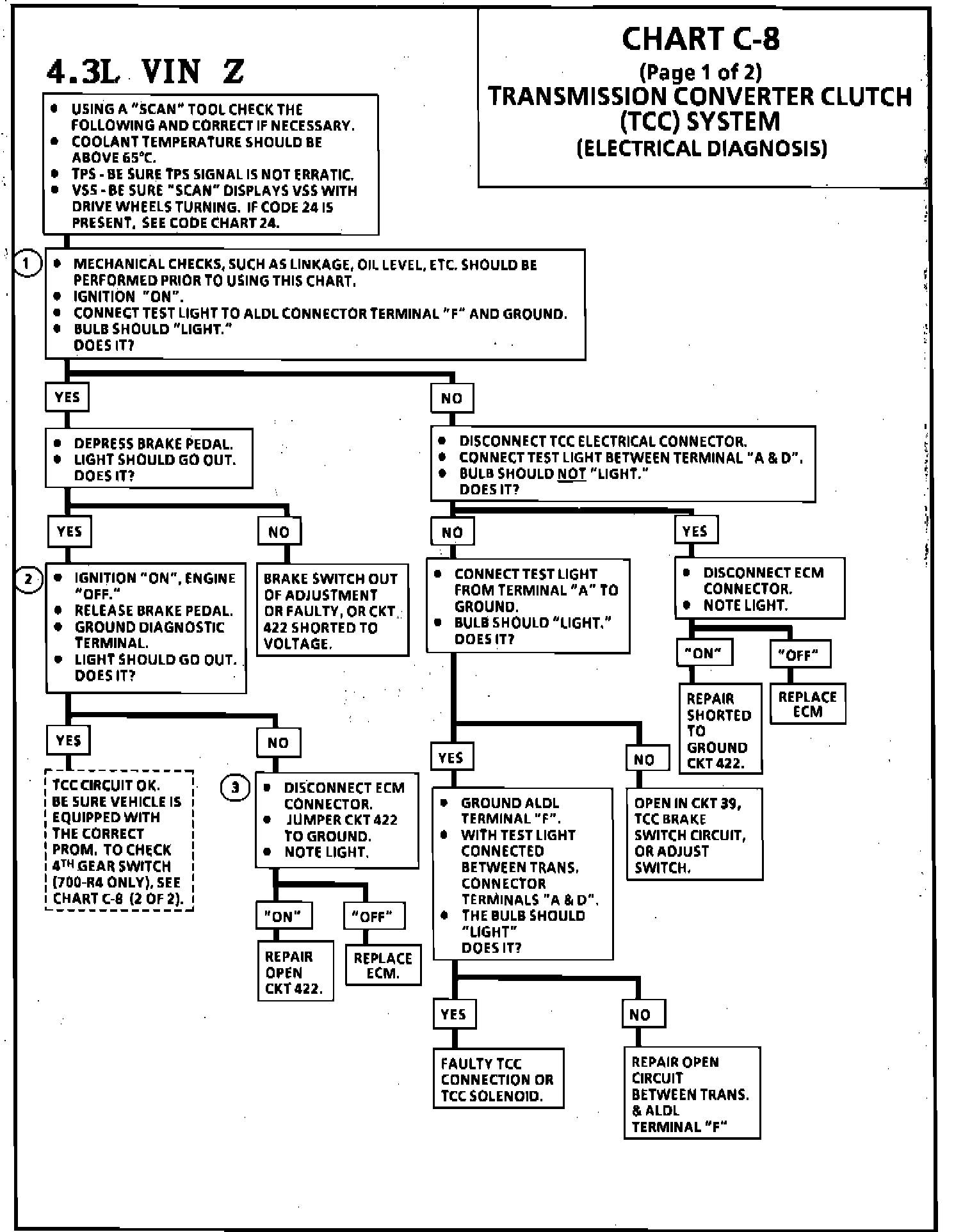
Test Description: Step numbers refer to step numbers on diagnostic chart.
1. Confirms 12 volt supply as well as continuity of TCC circuit.
2. Grounding the diagnostic terminal with engine "OFF", should energize the capability of the ECM to control the solenoid.
3. Solenoid coil resistance must measure more than 20 ohms. Less resistance will cause early failure of the ECM "Driver". Using an ohmmeter, check the solenoid coil resistance of all ECM controlled solenoids and relays before installing a replacement ECM. Replace any solenoid or relay that measures less than 20 ohms.
Diagnostic Aids: An engine coolant thermostat that is stuck open or opens at too low a temperature, may result in an inoperative TCC.
200-4R. If TCC engages before "Scan" indicates TCC "ON", wiring may be grounded between TCC solenoid and sump overtemp switch or switch may be faulty.
Fig. 005a Chart C-8A Transmission Converter Clutch:
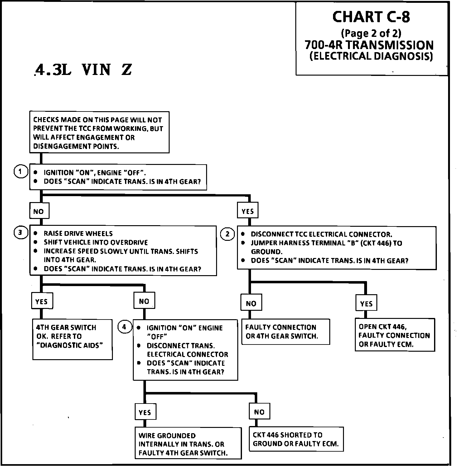
CHART C-8A
TRANSMISSION CONVERTER CLUTCH (TCC)
ELECTRICAL DIAGNOSIS
(Page 2 of 2)
4.3L "B/G" SERIES
FUEL INJECTION (TBI)
Circuit Description: A 4th gear switch (mounted in the transmission) opens when the trans shifts into 4th gear, and this switch is used to modify the TCC lockup points when in a 4-3 downshift.
Test Description: Step numbers refer to step numbers on diagnostic chart.
1. Unless CKT 466 or the switch is open the "scan" tool should display no indicating not in 4th gear. The switch should be open only in 4th gear.
2. Step 2 checks the wiring and ECM. with CKT 466 grounded the scan should display no (not in 4th gear).
3. This verifies that the 4th gear switch is working. The "scan " should display yes in 4th gear.
4. Disconnecting the TCC connector simulates an open switch to determine if CKT 446 is shorted to ground or the problem is in the transmission.
Diagnostic Aids: Road test the car and verify customer complaint. If the TCC is operating erratically on the "scan" check the 4th gear switch to be sure it is not changing under steady throttle position. If it is changing states check the connections and wire routing carefully. If the 4th gear switch is always open the TCC will engage as soon as there is sufficient oil pressure.