Stoplamp Switch - Revised Service Procedure: Overview
90chevy18Number: 90-159-5
Section: 5
Date: March 1990
Corp. Bulletin No.: 935012
Subject: NEW STOPLAMP SWITCH AND SERVICE PROCEDURE
Model and Year: 1990 W CARS
THIS BULLETIN CANCELS AND SUPERSEDES DEALER SERVICE BULLETIN NO. 90-60-5, DATED OCTOBER 1989. THE ADJUSTMENT CHECK HAS BEEN INCORPORATED WITH NEW SERVICE PROCEDURE. ALL COPIES OF 90-60-5 SHOULD BE DISCARDED.
A new stoplamp switch has been released for the 1990 model year, which services all previous model years. The new switch part number is 10180504 which is currently available from GMSPO.
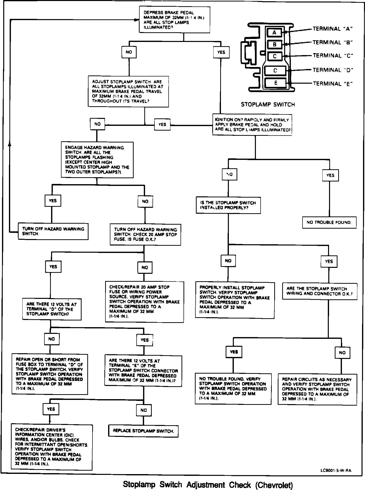
STOPLAMP SWITCH R&R
Refer to Switch Adjustment Check Procedure attached to determine if the switch operates properly.
The stoplamp switch procedure has been revised. The following procedures should be used when removing, installing or adjusting the stoplamp switch.
This procedure applies to the 1990 Chevrolet Lumina Service Manual Section 5, pages 5-6 and 5-7, please update your Service Manual.
Figure 1:
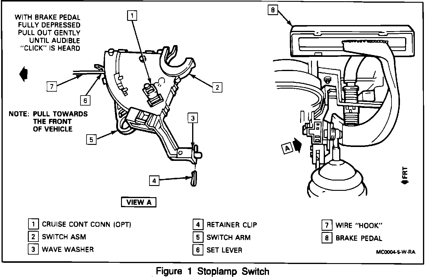
Figure 1
Remove or Disconnect
1. Air cleaner assembly, if necessary to access battery cables.
2. Negative battery cable.
3. Left side sound insulator panel.
- Slide steering shaft protective sleeve towards the cowl.
4. Air distribution tube and pull down.
5. Retainer clip which holds stoplamp switch to steering column bracket.
6. Switch arm from pedal by pushing the arm over and off of the brake pedal pin.
- Release switch by pulling down and releasing top snap clip.
7. Connector position assurance (CPA) locking pins from the four wire and two wire connector.
8. Two wire connector.
- Two wire connector is optional cruise control equipment.
9. Four wire connector.
10. Switch
Install or Connect
1. Two wire connector and CPA, if equipped with cruise control.
2. Switch
- Make sure brake switch is NOT adjusted (metal clip on actuator not engaged with serrations on bottom of carrier).
- Push switch up until seated into the top snap clip.
- Do NOT attach switch arm to pin on brake pedal at this time.
3. Retainer clip which holds stoplamp switch to steering column bracket.
- Push brake pedal down to floor pan and install switch arm over and onto brake pedal pin.
- Pull brake pedal all the way rearward and listen for the stoplamp switch to ratchet into the set position. At least three (3) clicks of the ratchet should be heard.
4. Four wire connector and CPA locking pin.
- Position steering shaft protective sleeve.
5. Negative battery cable.
Inspect
- Switch operation
- If the stoplamps do not operate, refer to "Stoplamp Switch Adjustment."
6. Left side sound insulator panel.
7. Air cleaner assembly, if removed.