Upper
Upper And Lower Intake Manifold Assemblies:
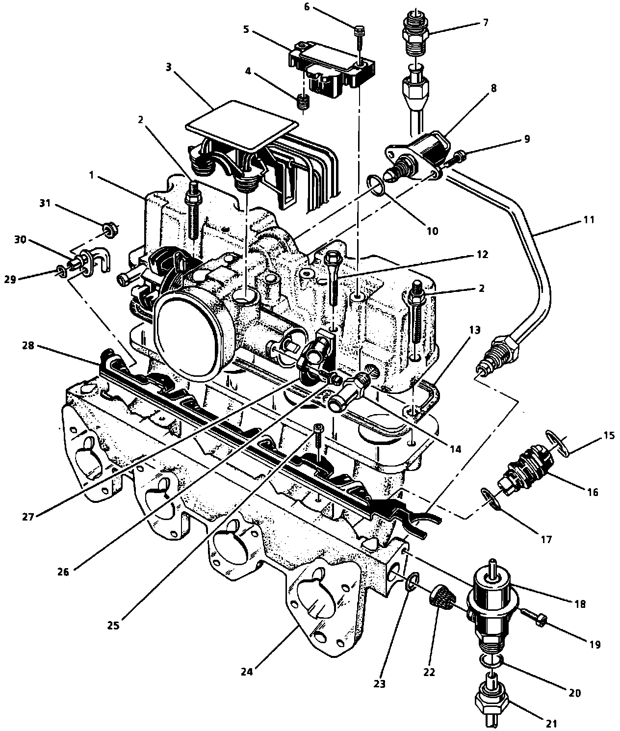
Upper And Lower Intake Manifold Assemblies - Legend:
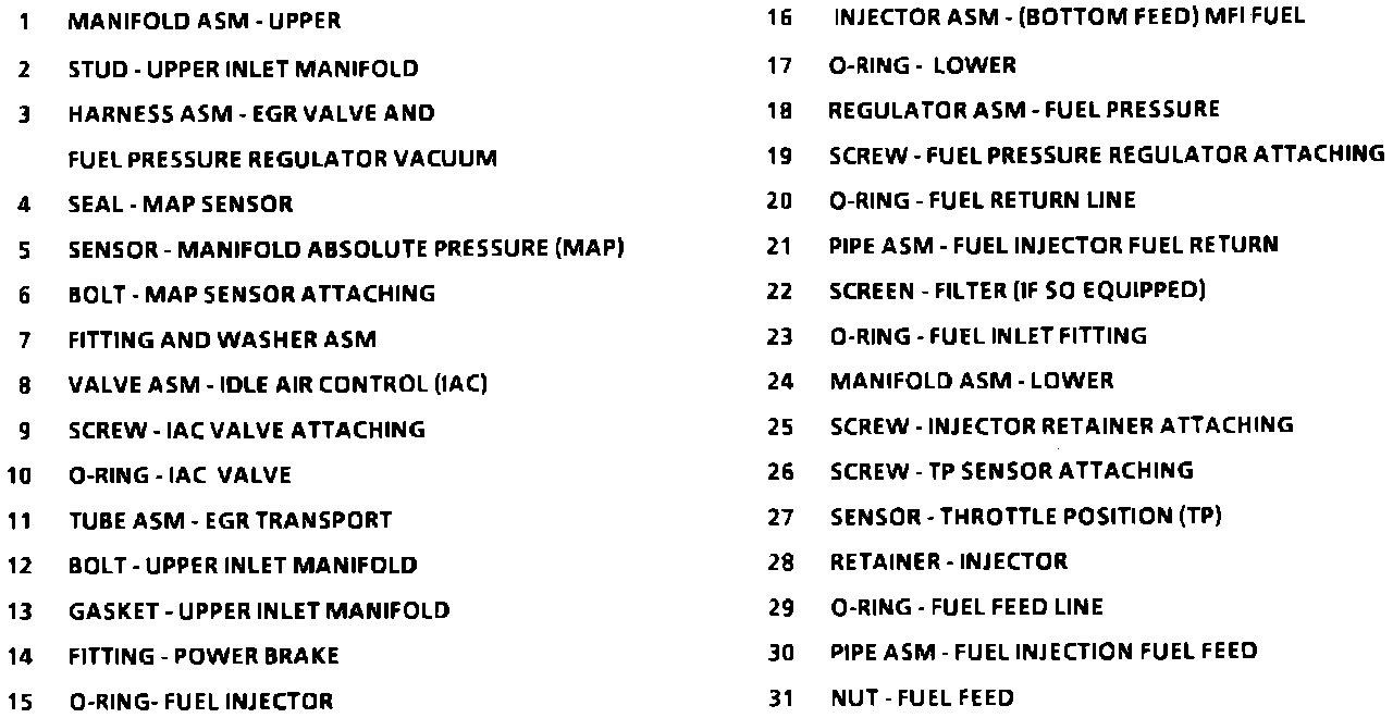
Identification Label Locations:
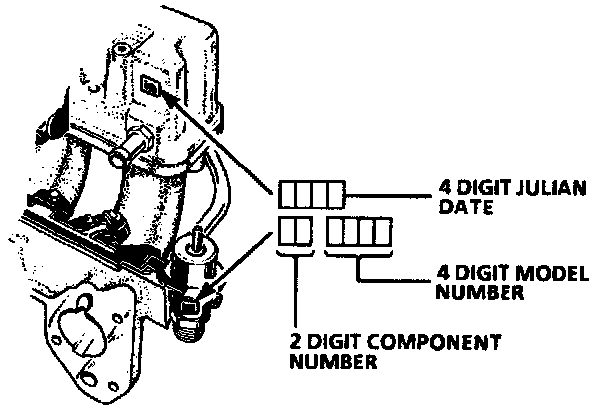
Upper Intake Manifold Assembly:
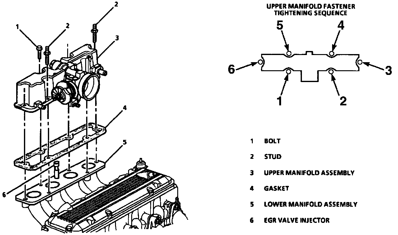
UPPER INTAKE MANIFOLD
A label containing the last four digits of the upper manifold assembly identification number appears above the power brake fitting assembly. The bar code (read by an optical scanner) also contains the component number for manifolds, and the four digits of the identifying number. Refer to this number if servicing or part replacement is required.
REMOVE OR DISCONNECT
1. Negative battery cable.
2. Air intake duct.
Accelerator Cable To Throttle Body:
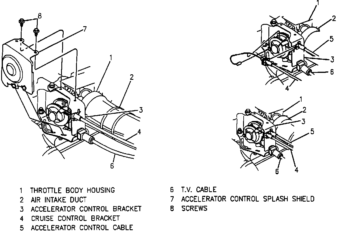
3. Accelerator cable splash shield from accelerator cable bracket.
4. Accelerator, cruise and transmission control cables.
5. Vacuum hose harness from top of air inlet.
6. PCV and power brake vacuum hoses from vacuum tubes at upper manifold and position vacuum hoses out of the way.
7. Electrical connectors at MAP sensor, TPS, and IAC valve.
8. Bolts/nuts attaching throttle cable bracket and position bracket and cables out of the way.
9. Bolts/studs attaching upper manifold to lower manifold and position EGR and injector wiring harness out of the way.
10. Upper manifold assembly and discard gasket.
11. Inspect replacement upper manifold for items that are to be transferred from unit removed from engine.
CAUTION: Use care in cleaning old gasket material from machined aluminum surfaces. Sharp tools may damage sealing surfaces.
Disassemble
1. Upper manifold, following component repair procedures.
2. Power brake vacuum fitting.
Assemble
1. Replacement upper manifold with transferred parts, following component repair procedures.
2. Power brake vacuum fitting, coated with appropriate thread-locking material and tighten to 13.0 Nm (115 lb in).
INSTALL OR CONNECT
1. Position EGR valve injector so that the port faces directly toward the throttle bore.
2. New upper manifold gasket.
3. Upper manifold assembly and reposition EGR and injector wiring harness.
4. Upper manifold attaching bolts/studs and tighten to 30.0 Nm (22 lb ft).
5. Accelerator cable bracket with attaching bolt/nuts and finger tighten only at this time.
CAUTION: The accelerator bracket must be aligned with the accelerator cam to prevent cable wear, which could result in cable breakage.
Accelerator Bracket Adjustment:
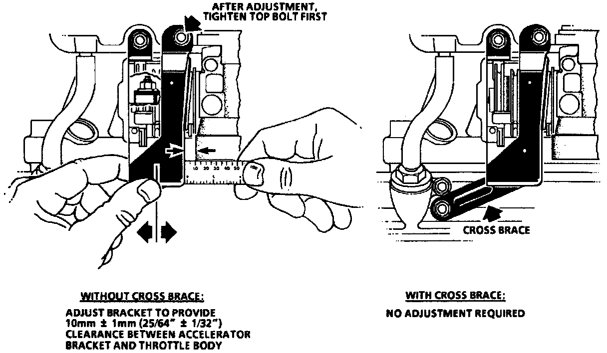
6. Adjust the accelerator cable bracket:
a. Place a steel rule across bore of throttle body, with one end in contact with accelerator bracket.
b. Adjust accelerator bracket to obtain a 10 mm ± 1 mm (25/64 ± 1/32) gap between bracket and throttle body.
c. Tighten accelerator cable bracket bolt/nuts to 25 Nm (18 lb ft). Top bolt must be tightened first.
7. Accelerator, cruise and transmission control cables.
8. Splash shield to accelerator bracket.
9. Electrical connectors to MAP sensor, TPS, IAC valve and EGR vacuum solenoid.
10. Vacuum hose harness to top of air inlet.
11. Connect PCV and power brake vacuum hoses to vacuum tubes at upper manifold.
12. Turn ignition switch to the "ON" position for two seconds, then turn to the "OFF" position for ten seconds. Again turn to the "ON" position, and check for fuel leaks.
13. Negative battery cable.
14. Air intake duct.