Central Control Module (CCM)
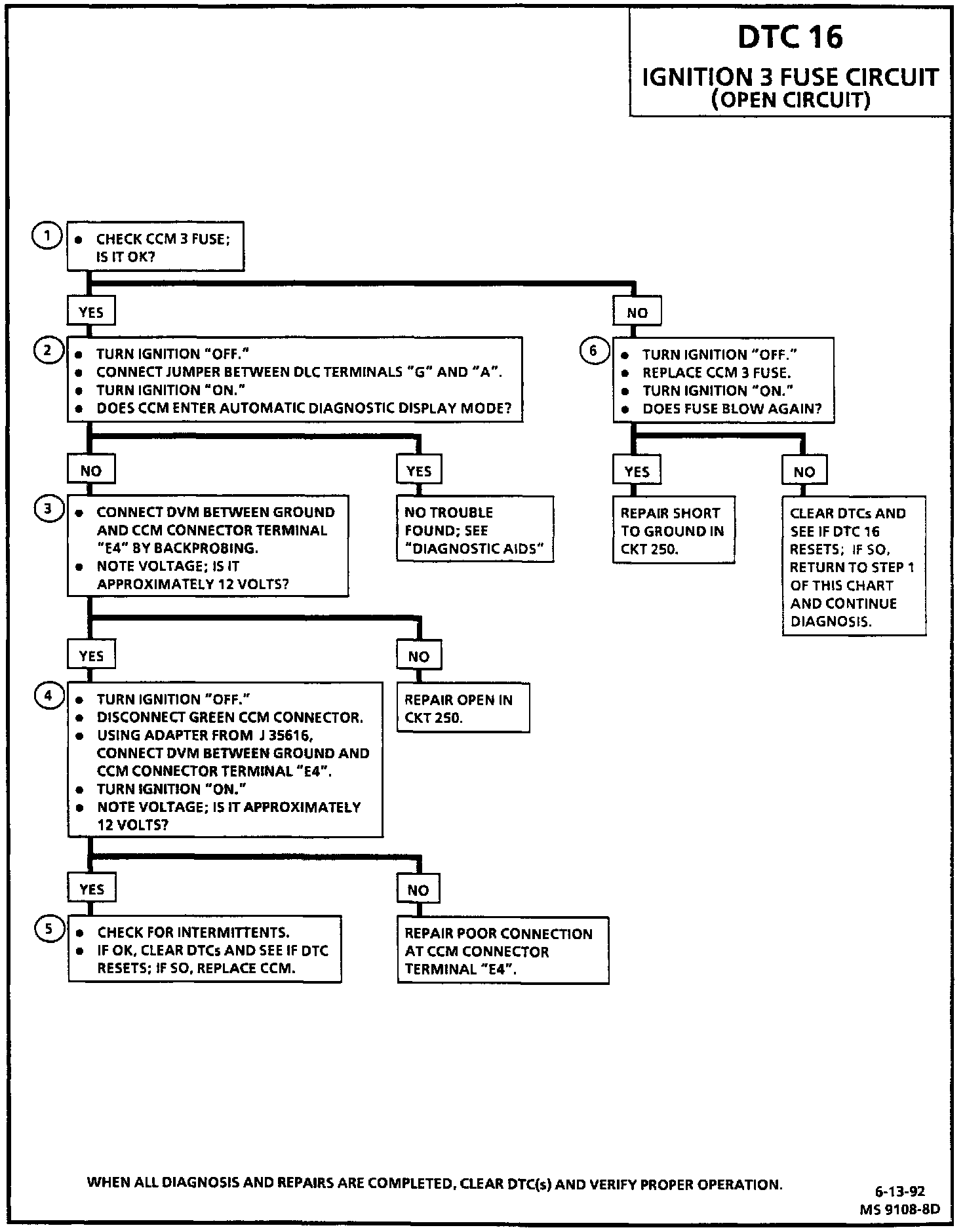
Diagnostic Chart:
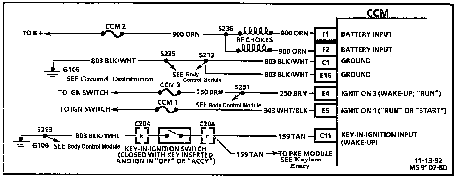
Wiring Diagram:
CIRCUIT DESCRIPTION
The Ignition 3 fuse circuit is at system voltage when the ignition switch is in the "RUN" position only, and open otherwise.
If the Ignition 3 fuse circuit is low for more than 3 seconds when the CCM expects it to be high, DTC 16 will set. DTC 16 will always be a history DTC; see "Diagnostic Aids."
TEST DESCRIPTION
Number(s) below refer to circled number(s) on the diagnostic chart.
1. This checks to see if the fuse is blown.
2. This test checks to see if the CCM is receiving IGN 3 power from CKT 250; the CCM requires IGN 3 to enter its diagnostic mode.
3. This test checks to see if the wiring up to the CCM connector terminal and the terminal-to-wire contact is good.
4. This test uses a mating terminal adapter as a test of the contact tension of CCM connector terminal "E4".
5. This test checks for intermittents and the possibility of a malfunctioning CCM.
6. This test checks for a short to ground in CKT 250.
DIAGNOSTIC AIDS
This DTC will always appear as a history DTC. IGN 3 power is required for the CCM to enter its diagnostic mode. Therefore, with the CCM 3 fuse blown, as it would need to be for the DTC to show up as current, the CCM could not enter diagnostic mode to show the DTC.
Try performing tests shown while "wiggling" wiring and connectors if the malfunction seems to be intermittent; this can often cause the fault to appear.
Many other components/systems may be inoperative if the CCM 3 fuse is blown or CKT 250 is bad. Refer to DIAGRAMS in "Power and Ground Distribution" for the other items using the CCM 3 fuse. Electrical Diagrams