Central Control Module (CCM)
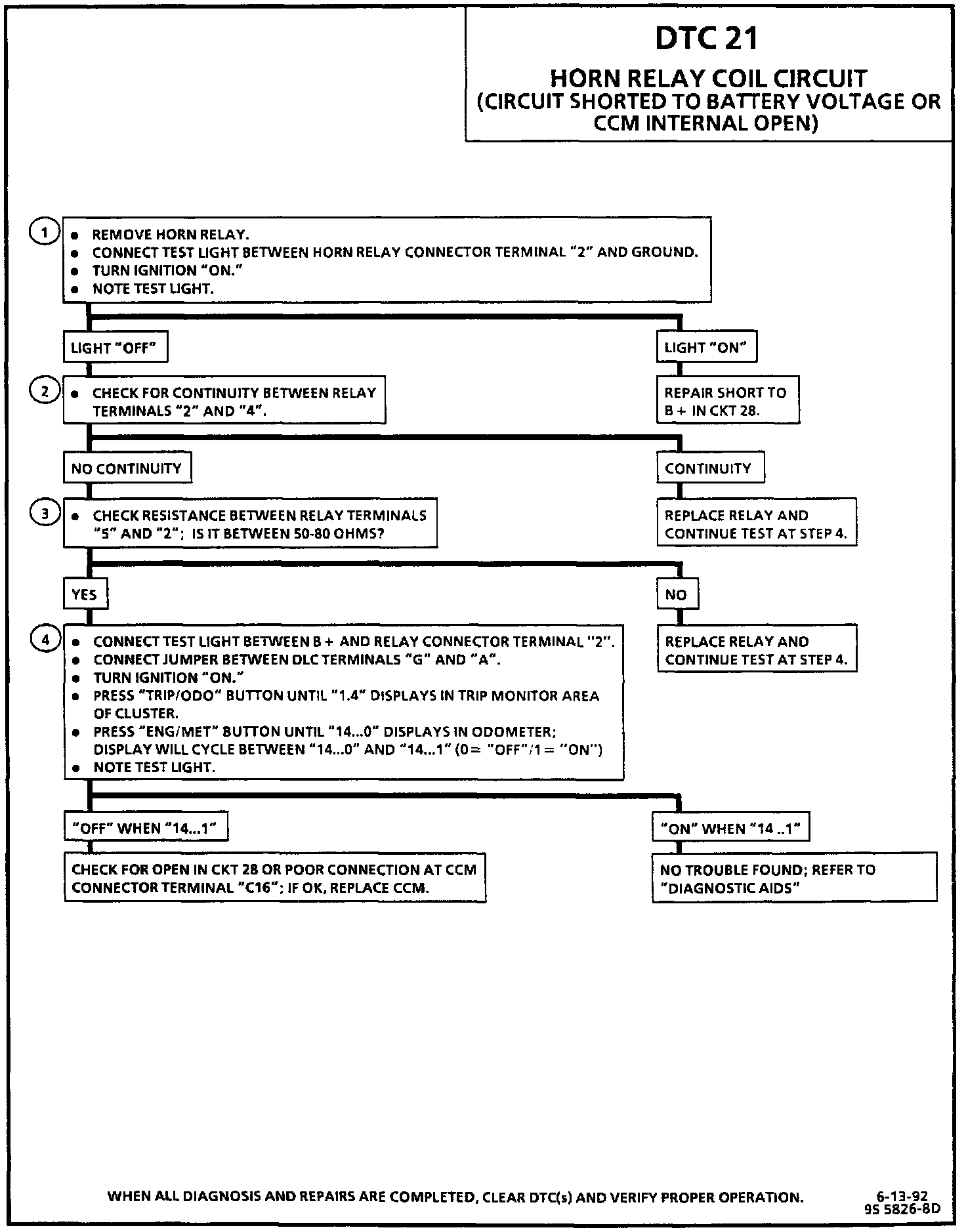
Diagnostic Chart:
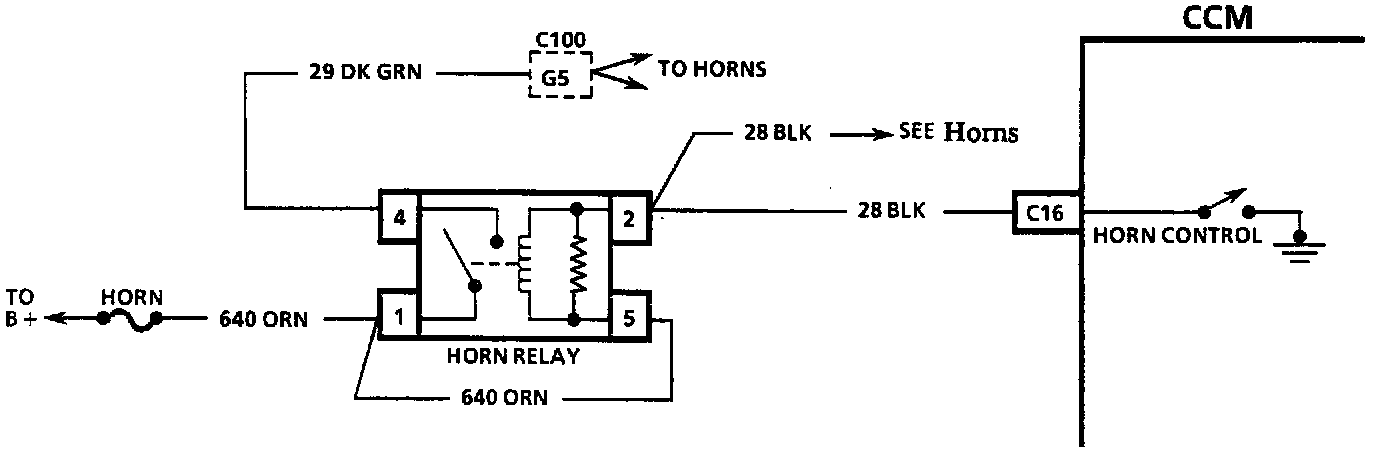
Wiring Diagram:
CIRCUIT DESCRIPTION
The horn relay coil circuit is part of a "standard" horn system, except for the addition of CCM control of the system through CKT 28. The CCM can activate the horns if the anti-theft system signals it to do so; the CCM completes the ground for the relay coil circuit. normally provided through the horn switch on the steering wheel.
DTC 21 will set when CKT 28 is in a high state (not grounded by the CCM) for more than 600 milliseconds while the CCM is attempting to actuate the horn control relay.
TEST DESCRIPTION
Number(s) below refer to circled number(s) on the diagnostic chart.
1. This test checks for a short to B+ in CKT 28.
2. This test checks for an internal short in the relay between terminals "2" and "4", which would cause a short to battery condition by allowing power from the HORN fuse into the circuit.
3. This test checks for an internal open in the relay.
4. This test checks for proper CCM control of the circuit by telling the CCM to cycle the ground at terminal "2" "ON" and "OFF." If the connection at the CCM, the wiring, and the relay connector are good but the test light does not cycle "ON" and "OFF," the CCM is malfunctioning and should be replaced.
DIAGNOSTIC AIDS
If the DTC is a history DTC, the problem may be intermittent. Try performing the tests shown while "wiggling" wiring and connectors; this can often cause the malfunction to appear. Check for poor connections at both the CCM arid the horn relay connector; these could cause an open or an intermittent malfunction. Refer to "Intermittents and Poor Connections" in DIAGRAMS.
If this DTC is present, the horn will not sound even though the Universal Theft Deterrent (UTD) system is attempting to do so.