Central Control Module (CCM)
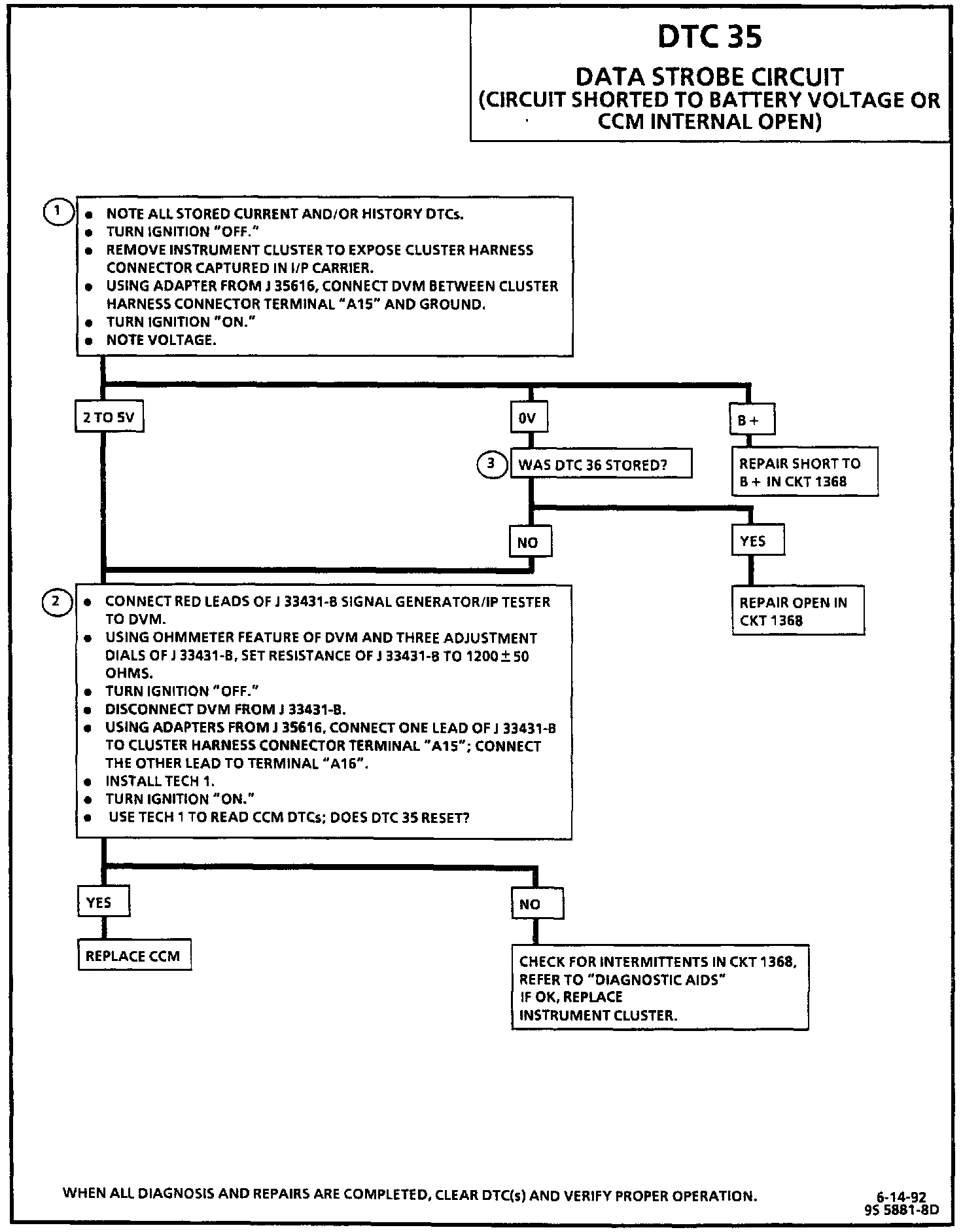
Diagnostic Chart:
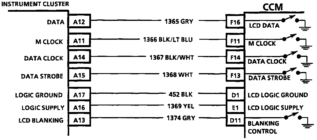
Wiring Diagram:
CIRCUIT DESCRIPTION
The data strobe circuit provides the timing signal which causes the contents of the Liquid Crystal Display's (LCD's) buffer to be displayed. This occurs after all 160 bits have been clocked into the LCD's buffer.
Upon power-up, the CCM pulls CKT 1368 low. If it is high during the next 40 milliseconds, DTC 35 will set.
TEST DESCRIPTION
Number(s) below refer to circled number(s on the diagnostic chart.
1. This test checks for a good signal to the instrument cluster from the CCM.
2. This test replaces the cluster with a 1200 ohm resistance very similar to the resistance of the cluster. If the DTC comes back. the CCM must be Malfunctioning. If the DTC does not come back, the cluster must be the source of the problem.
3. This test checks for another DTC being set. If that DTC was set, it is possible that the problems which set that DTC also set this one.
DIAGNOSTIC AIDS
If there is a short to B+ or the CCM is internally open, random characters will be displayed and the cluster display will be "frozen."
If the DTC is a history DTC, the problem may be intermittent. Try performing the tests shown while "wiggling" wiring and connectors; this can often cause the malfunction to appear. Refer to "Intermittents and Poor Connections" in DIAGRAMS.