Central Control Module (CCM)
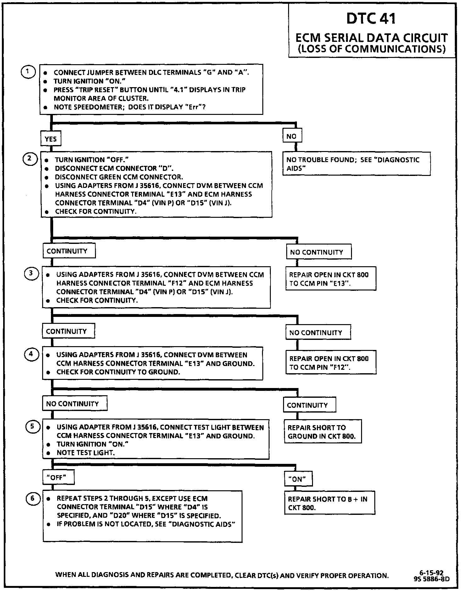
Diagnostic Chart:
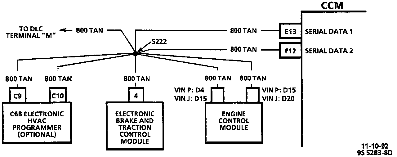
Wiring Diagram:
CIRCUIT DESCRIPTION
The serial data circuit is a communications link between the CCM, ECM, Electronic Brake and Traction Control Module (EBTCM), and C68 HVAC programmer, if equipped. It is a master/slave configuration, with the CCM acting as master, and all the other devices communicating with each other through the CCM.
DTC 41 will set if the ECM does not respond to CCM polls for more than a certain time period. DTC 41 being set will also prohibit Fuel Enable Data Stream (FEDS) fuel enable from taking place (see DTC 54). Central Control Module (CCM)
TEST DESCRIPTION
Number(s) below refer to circled number(s) on the diagnostic chart.
1. This test determines if the CCM is having a problem communicating with the ECM.
2. This test checks for an open between serial data 1 of the CCM and ECM serial data line 1.
3. This test checks for an open between serial data 2 of the CCM and ECM serial data line 1.
4. This test checks for a short to ground in CKT 800.
5. This test checks for a short to battery in CKT 800.
6. This test repeats Tests 2 through 5 using ECM serial data line 2 rather than line 1.
DIAGNOSTIC AIDS
A short circuit on the serial data link will take the whole link down; an open circuit will take down only those devices which become open-circuited.
A serial data malfunction may also cause an inoperative trip computer, loss of english/metric temperature display control on the C68 electronic HVAC control head, and loss of the "Check Gauges" function.
If this fault is present, a C68 electronic HVAC control head Light Emitting Diode (LED) will flash.
Check for an ECM DTC 51, which will cause this DTC to set. The ECM DTC 51 problem will also be evidenced by the inability to flash ECM DTCs or to read ECM DTCs through the CCM.