Central Control Module (CCM)
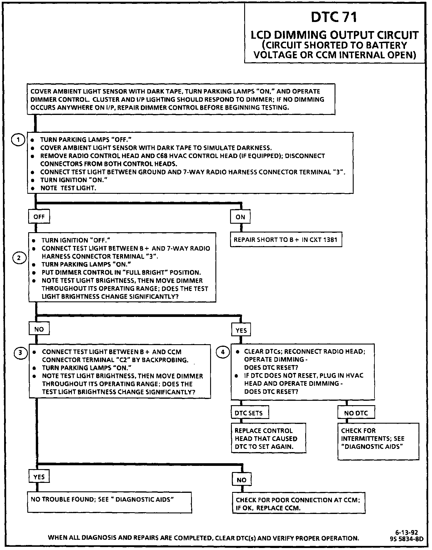
Diagnostic Chart:
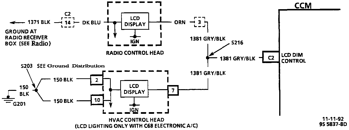
Wiring Diagram:
CIRCUIT DESCRIPTION
The Liquid Crystal Display (LCD) dimming output circuit, which controls the back lighting on the radio control head (and the HVAC control head when equipped with C68 Electronic Climate Control), receives its ground in the form of a PWM output from the CCM through CKT 1381. Power is supplied to the circuit internally through the radio control head and HVAC control head if equipped).
When the CCM is powered up, the LCD dimming output circuit is pulled to a low state by the CCM. If after 60 milliseconds the CCM senses the line is not at a low state, DTC 71 will set.
TEST DESCRIPTION
Number(s) below refer to circled number(s) on the diagnostic chart.
1. This test checks for a short to B+ in CKT 1381.
2. This test checks for proper operation at the radio control head end of the circuit.
3. This test checks for proper operation of the circuit at the CCM; if there is a problem and the connection is OK, replace the CCM.
4. This test reconnects each of the possible problem parts back into the system one by one; if a DTC resets after a certain device is plugged back into the circuit, that device is causing the malfunction and should be replaced.
DIAGNOSTIC AIDS
If the DTC is a history DTC, the problem may be intermittent. Try performing the tests shown while "wiggling" wiring and connectors; this can often cause the malfunction to appear. Check for poor connections at the CCM, the radio control head, and the HVAC control head (if equipped with C68 Electronic Climate Control); these could cause an open or an intermittent malfunction. Refer to "Intermittents and Poor Connections" in DIAGRAMS.
This DTC will only set if the dimming request IS NOT 0% (full bright) or 100% (full dim). Also, the dimming circuit must be active for the DTC to set, i.e., the headlamps or parking lamps must be "ON" and some level of dimming must be requested.