Torque Converter Clutch: Testing and Inspection
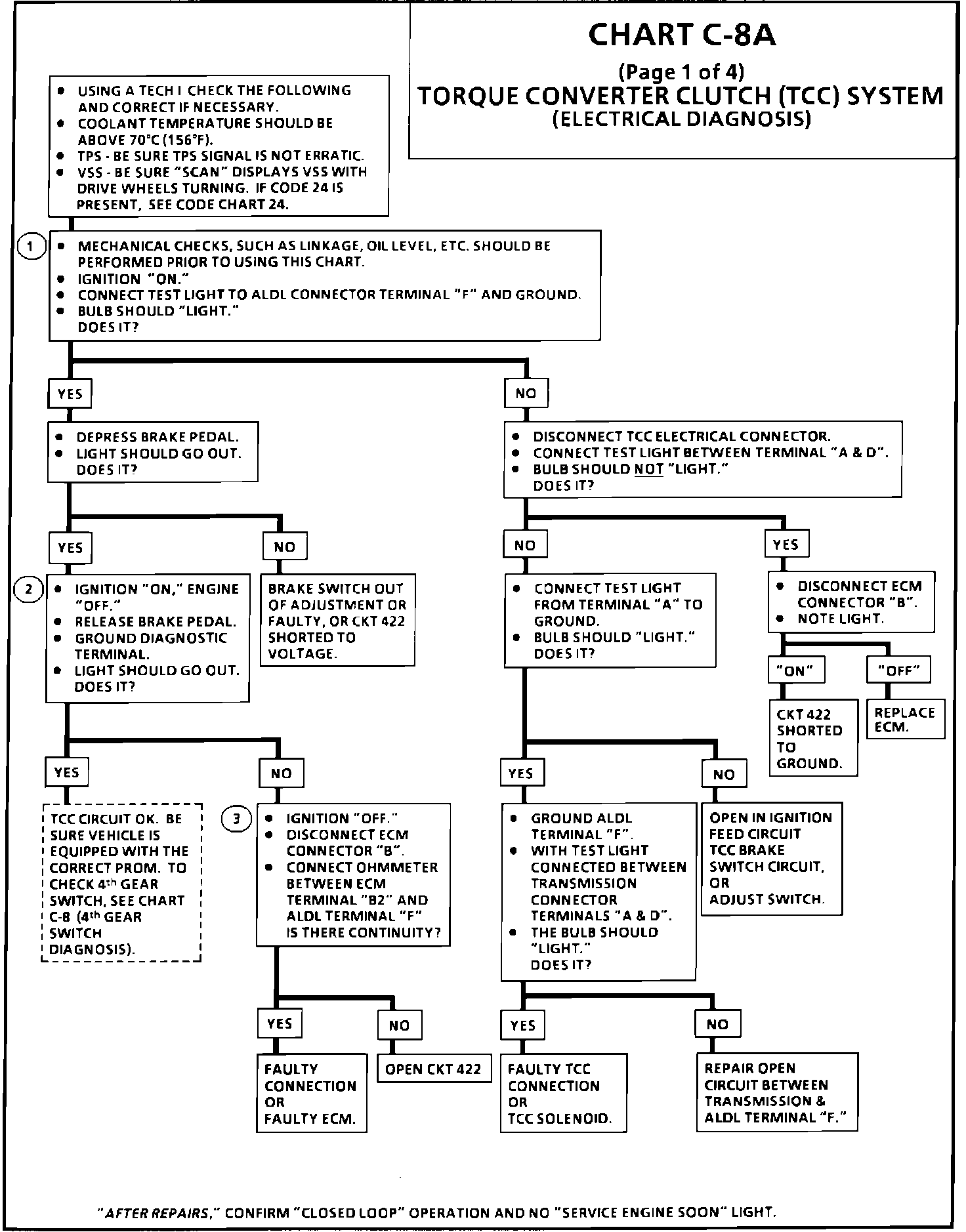
Chart C-8A, 1 Of 4 (TCC Electrical Diagnosis):
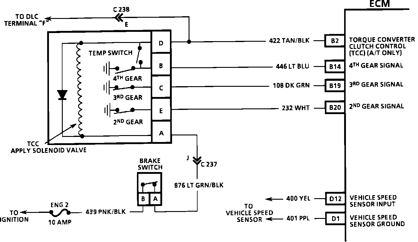
TCC And Gear Switch Circuit Diagram:
CIRCUIT DESCRIPTION:
The purpose of the [1][2]torque converter clutch feature is to eliminate the power loss through the torque converter when the vehicle is in a cruise condition. This allows the convenience of the automatic and the fuel economy of a manual transaxle. A computer controlled solenoid valve applies fluid pressure to the TCC when energized, engaging the clutch.
When the TCC solenoid is turned "ON", the [1][2]torque converter clutch is applied, making a mechanical coupling between the engine and transmission. When the solenoid is deactivated, the torque converter clutch is released and the torque converter operates in the conventional manner (fluid coupling between engine and transaxle).
The ECM turns the TCC solenoid "ON" when coolant temperature is above 65°C (149°F), TPS signal is constant, and vehicle speed above a specified value.
TEST DESCRIPTION
Numbers below refer to circled numbers on diagnostic chart.
1. Confirms 12 volt supply as well as continuity of TCC circuit.
2. When the diagnostic test terminal is grounded, the ECM should energize the TCC solenoid.
3. TCC solenoid coil resistance must measure more than 20 ohms. Less resistance will cause early failure of the ECM driver. Using an ohmmeter, check the solenoid coil resistance of all ECM controlled solenoids and relays before installing a replacement ECM. Replace any solenoid or relay that measures less than 20 ohms.
DIAGNOSTIC AIDS:
The "Scan" tool only indicates when the ECM has turned "ON" the TCC driver and this does not confirm that the TCC has engaged. To determine if TCC is functioning properly, road test the vehicle. Engine rpm should decrease when the "Scan" indicates the TCC driver has turned "ON." To determine if the gear switches are functioning properly, perform the checks in parts 2, 3, and 4 of this diagnostic sequence. The switches will not prevent the TCC from functioning, but will affect TCC lock and unlock points. If the 4th gear switch circuit is always open, the TCC may engage as soon as sufficient fluid pressure is reached.