Unit Repair
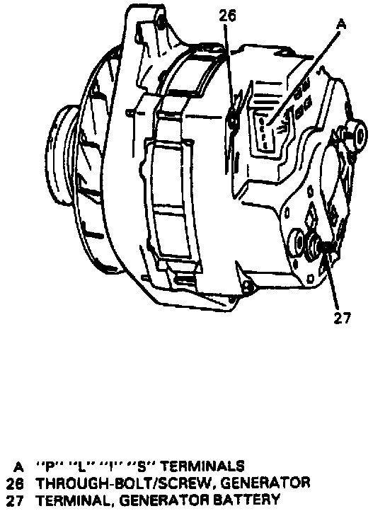
Generator Through-Bolt/Screw Location:
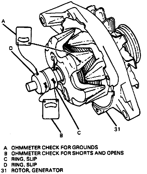
Testing Generator Rotor:
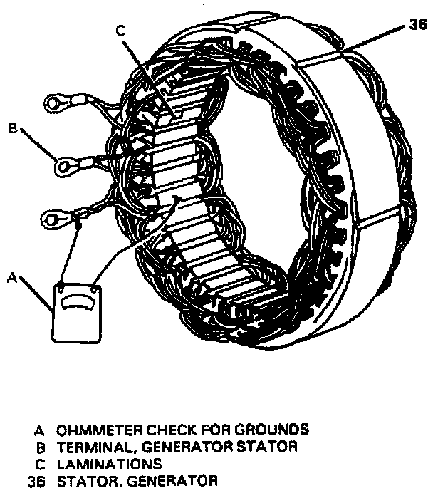
Testing Generator Stator:
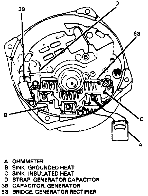
Testing Generator Rectifier Bridge:
Generator Rotor Drive End Bearing:
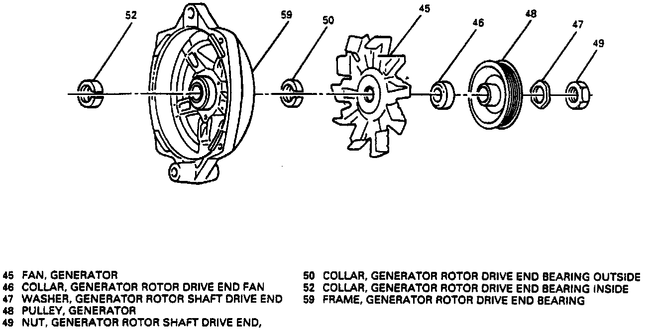
Generator Slip Ring End Frame Components:
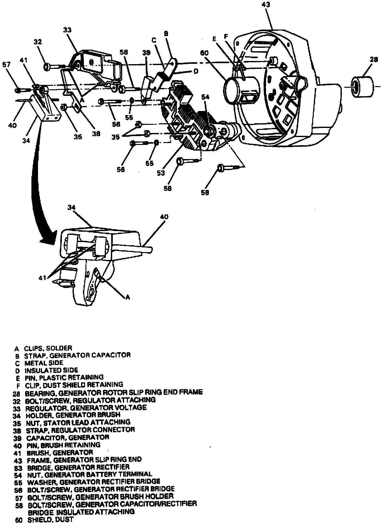
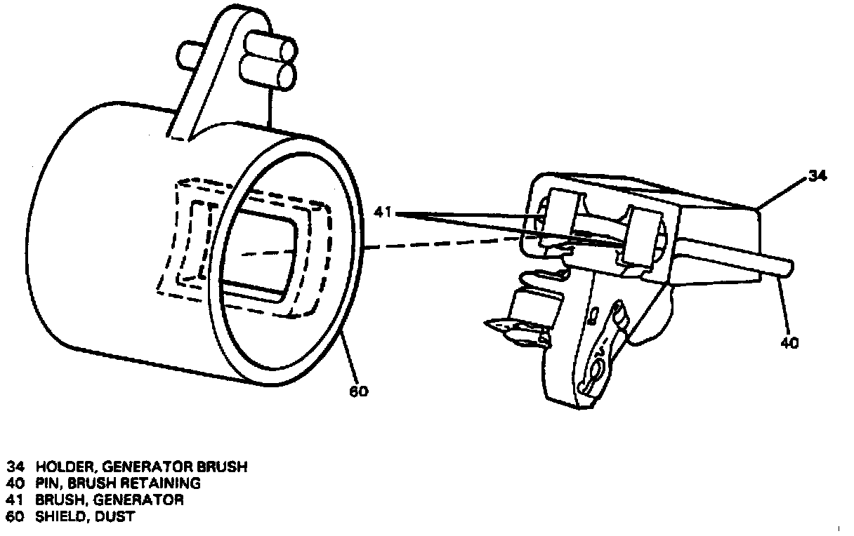
Generator Brushes Retained In Generator Brush Holder:
Generator Slip Ring End Frame View:
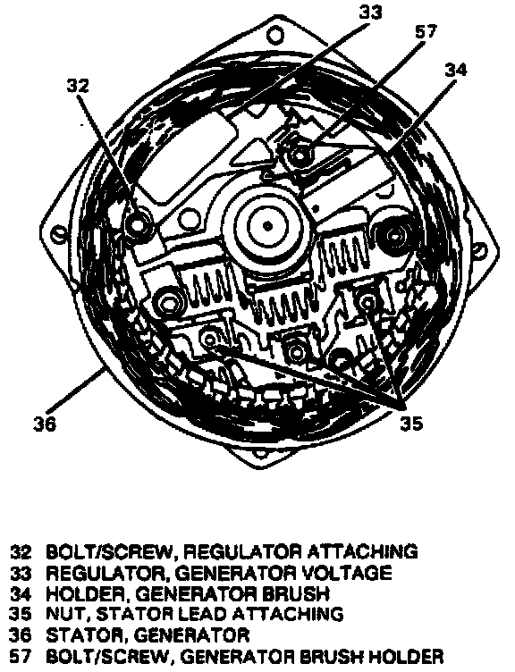
Removing Generator Voltage Regulator And Generator Brush Holder:
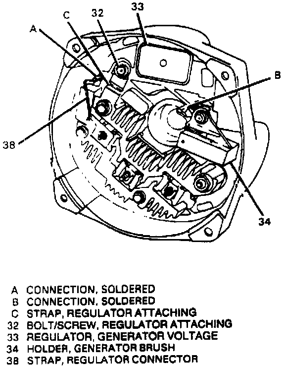
DISASSEMBLE
1. Make scribe marks on slip ring end frame (43) and drive end frame (59) to ease re-assembly.
2. Through-bolts/screws (26) and separate slip ring end frame (43) and drive end frame (59).
3. End frame bearing (28) from rotor shaft.
Measure
^ Rotor (31) for grounds, opens and shorts.
Important: Test should be performed at approximately 21°C (70°F). A different temperature may result in inaccurate ohmmeter readings.
A. Connect ohmmeter to slip ring and clean metal grounding surface on frame of rotor (31) to check for grounds.
^ Ohmmeter should read infinity (open). If not, replace rotor (31).
B. Connect ohmmeter to both slip rings to check for shorts and opens.
^ Ohmmeter should read 1.7 to 2.1 ohms. If not, replace rotor (31).
4. Nuts (35).
5. Stator (36) from slip ring end frame (43).
Measure
^ Stator (36) for grounds.
A. Connect ohmmeter to stator terminal and to clean metal ground on laminations.
B. If ohmmeter reading is low, replace stator (36). Stator (36) cannot he checked for opens and shorts with ohmmeter.
6. Unsolder connections at connector strap (38) and brush holder (34) to voltage regulator (33).
7. Bolt/screw (32) and bolt/screw (57).
8. Voltage regulator (33) and brush holder (34) with dust shield (60) from slip ring end frame (43).
^ Tap plastic retaining pin from dust shield retaining clip. Be sure to keep pin for assembly.
9. Brushes (41) and dust shield (60) from brush holder (34).
Clean
^ Brushes (41) with soft, dry cloth.
Measure
^ Rectifier bridge (53) for continuity.
A. Connect ohmmeter to grounded heat sink and flat metal clip at rectifier bridge (53).
B. Reverse leads. One reading should be high (open) and one low (continuity). If both readings are the same, replace rectifier bridge (53).
C. Repeat test between grounded heat sink and clips at two other bridge terminals.
D. Repeat test between insulated heat sink and at bridge terminals.
10. Capacitor (39) and rectifier bridge (53).
11. Washers (55) and bolts/screws (56 and 58).
12. Bearing (28) from slip ring end frame (43) by pushing through to inside.
13. Nut (49), using hex wrench to hold rotor shaft.
14. Washer (47), pulley (48), fan collar (46), fan (45) and outside collar (50).
15. Rotor (31) from drive end frame (59).
16. Inside collar (52) from rotor (31).
ASSEMBLE
NOTICE: Refer to "Service Precautions".
1. Inside collar (52) onto rotor (31).
2. Rotor (31) to drive end frame (59).
3. Outside collar (50), fan (45), fan collar (46), pulley (48) and washer (47) onto rotor shaft.
4. Generator rotor shaft drive end nut (49).
Tighten
^ Generator rotor shaft drive end nut (49) to 100 N.m (75 lb. ft.).
5. Bearing (28) into slip ring end frame (43) from outside, until flush with outside shoulder of slip ring end frame (43).
6. Slip ring end frame electrical components.
Important
^ Installation of the slip ring end frame electrical components must he done in the following order to insure proper operation of the unit. Assembly in any other manner will result in either no output from generator (S) or a direct internal ground in the generator (5).
A. Rectifier bridge (53).
B. Capacitor (39).
C. Washers (55).
D. Bolts/screws (56 and 58).
Important
^ The capacitor (39) has an insulator material on one side which must rest against the drive end frame (59) (ground).
^ The capacitor/rectifier bridge insulated attaching bolt/screw (58) must he installed in the proper hole, attaching the capacitor strap and rectifier bridge (53) to the slip ring end frame (43).
E. Brushes (41) into brush holder (34) with retaining pin (40).
E. Dust shield (60) onto brush holder (34).
G. Voltage regulator (33), and brush holder (34) with dust shield (60), brushes (41) and retaining pin (40) installed into slip ring end frame (43).
Important: The metal side of the capacitor strap must he against the regulator connection.
H. Tap plastic retaining pin on dust shield (60) into retaining clip.
^ Be sure brush retaining pin (40) goes through access hole to outside of slip ring end frame (43) for removal after generator is reassembled.
I. Bolt/screw (32) and bolt/screw (57).
J. Connector strap (38) to voltage regulator solder clip, and brush holder connection to other voltage regulator solder clip.
^ Crimp and solder voltage regulator solder clip connections.
NOTICE: Avoid excessive heat when soldering connections, as this can cause voltage regulator damage.
K. Stator (36), placing stator terminals over rectifier bridge terminals.
L. Nuts (35).
M. Slip ring end frame (43) and drive end frame (59), noting scribe marks.
N. Slip ring end bearing outer race into bearing well in slip ring end frame casting.
O. Through-bolts/screws (26).
P. Remove retaining pin (40) to release brushes (41) against slip rings.