Case Cover
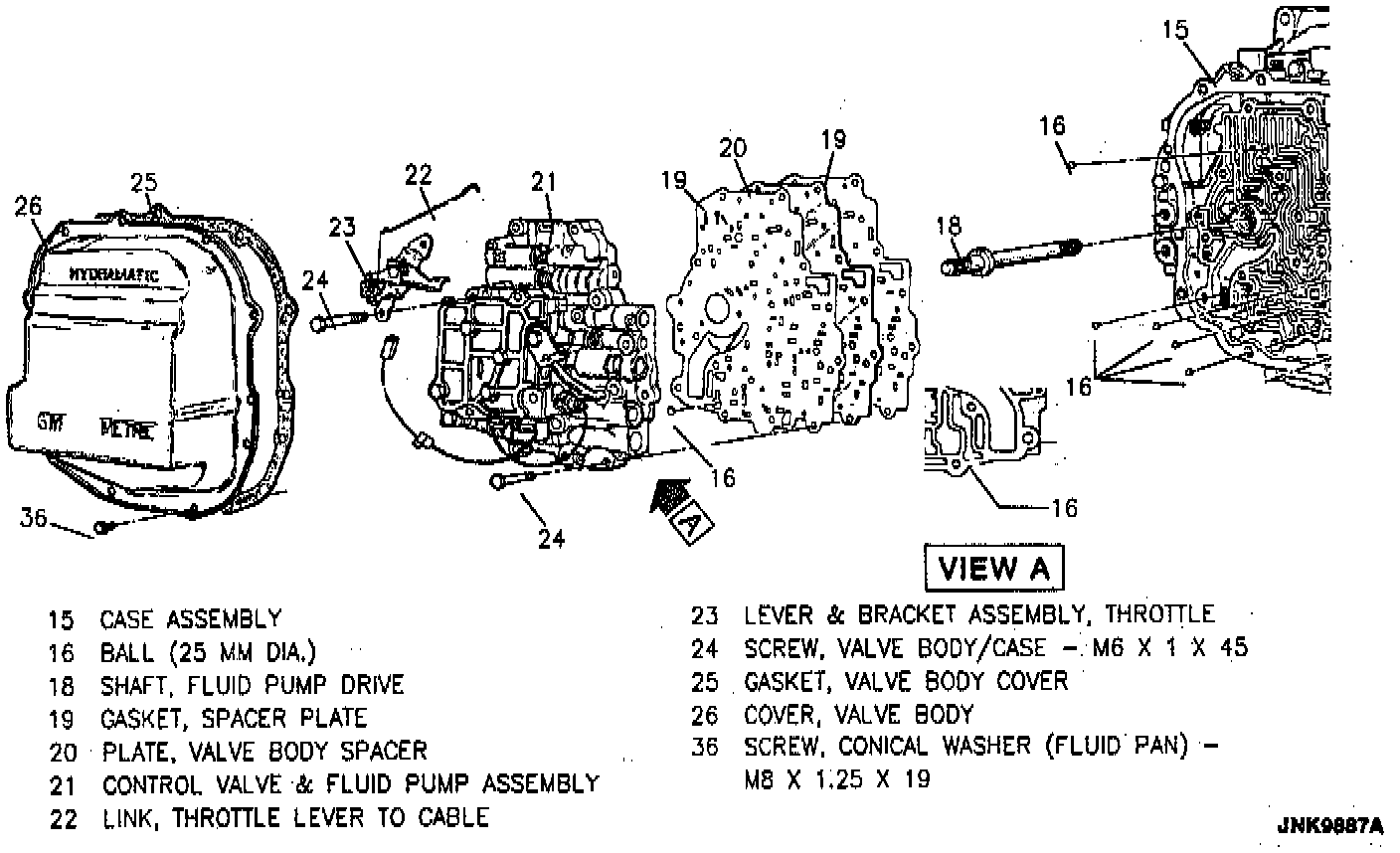
^ Tool Required:
- J 28467-360 Engine Support Fixture
REMOVE OR DISCONNECT
1. Negative battery cable.
2. Transaxle bracket, refer to "Transaxle Support Assembly."
3. Valve body cover, refer to "Valve Body Cover."
4. TCC wires from case connector.
5. Control valve and oil pump assembly from case cover. Refer to HYDRA-MATIC for appropriate bolts to remove.
Important
- Do not lose check balls.
6. Oil pump drive shaft.
7. Spacer plate and gaskets.
8. Case cover.
- Install two 12 x 1.95 x 14 bolts in dowel pin holes and tighten equally to pull case cover loose.
Important
- When disassembling a Hydra-Matic , inspect the drive link assembly for wear. Refer to "Drive Link Assembly."
INSTALL OR CONNECT
1. Case cover. Tighten bolts to 24 N.m (18 lb ft).
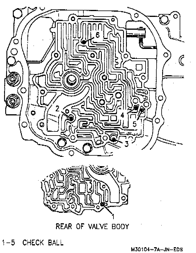
2. Check balls into case cover, refer to the image.
3. Spacer plate and gaskets.
4. Pump drive shaft.
5. Check ball into control valve assembly.
6. Auxiliary valve body and control valve assembly onto transaxle.
7. TCC wire to case electrical connector.
8. Valve body cover, refer to "Valve Body Cover."
9. Transaxle mount bracket, refer to "Transaxle Support Assembly."
10. Negative battery cable.