Brake Pads Replacement (Front)
REMOVAL PROCEDURE1. Remove two-thirds of the brake fluid from the master cylinder reservoir.
2. Raise and suitably support the vehicle.
3. Remove the tire and wheel assembly.
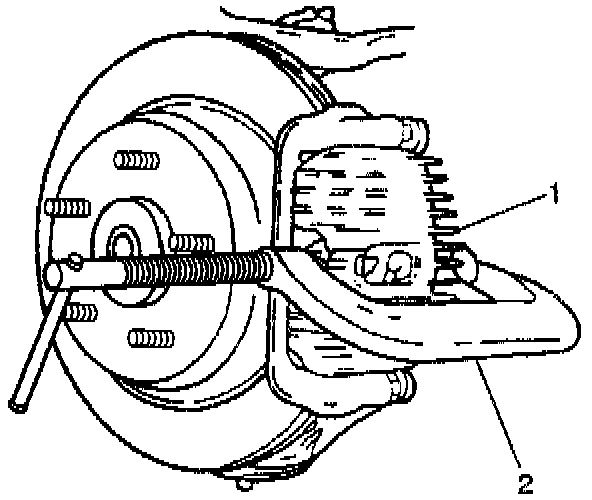
4. Install C-clamp onto front brake caliper and tighten until the caliper pistons bottom in the caliper housing. Verify that the C-clamp is centrally positioned on both the caliper housing and the brake pad. This provides an even clamping force on both pistons and should prevent the pistons from becoming wedged in their bores due to uneven clamping force.
5. Remove front brake caliper. Refer to Brake Caliper Replacement (Front).
6. Remove the inner and outer brake pads from the caliper mounting plate.
Use a screwdriver if necessary to remove the pads from their installed position.
7. Inspect the caliper guide pins for free movement in the caliper mounting plate.
8. Inspect the caliper guide pin boots for proper seating in the retaining groove of the caliper guide pin and the rear caliper mounting plate.
9. Replace the caliper guide pins and/or guide pin boots if any of the following conditions exist:
^ Excessive Corrosion
^ Excessive Wear
^ Visible Damage
INSTALLATION PROCEDURE
Important: Use GM replacement brake pads for all GM vehicles in order to maintain the balance in performance between the front and rear brakes. GM replacement brake parts are carefully selected in order to guarantee minimum stopping distance and maximum controllability over the full range of operating conditions. Installing front or rear brake pads not recommended by GM may change the intended performance, wear characteristics, and brake balance of the vehicle.
1. Install the inner and outer pads into the caliper mounting plate. Ensure that the wear sensor is at the trailing edge of the outer brake pad when the wheel is rotating forward. If the wear sensor is not at the trailing edge, the outer brake pad is on the wrong side.
2. Install the front brake caliper. Refer to Brake Caliper Replacement (Front).
NOTICE: Always use the correct fastener in the proper location. When you replace a fastener, use ONLY the exact part number for that application. The manufacturer will call out those fasteners that require a replacement after removal. The manufacturer will also call out the fasteners that require thread lockers or thread sealant. UNLESS OTHERWISE SPECIFIED, do not use supplemental coatings (paints, greases, or other corrosion inhibitors) on threaded fasteners or fastener joint interfaces. Generally, such coatings adversely affect the fastener torque and joint clamping force, and may damage the fastener. When you install fasteners, use the correct tightening sequence and specifications. Following these instructions can help you avoid damage to parts and systems.
3. Install the caliper mounting pin bolts.
Tighten the mounting pin bolts to 31 Nm (23 ft. lbs.).
4. With the engine running, pump the brake pedal slowly and firmly until the inner and outer brake pads are positioned against rotor (firm pedal).
5. Install the tire and wheel assembly.
6. Lower the vehicle.
7. Refill the master cylinder to the proper level with clean, fresh brake fluid.
8. Inspect the hydraulic brake system for brake fluid leaks.