Lower Control Arm Replacement
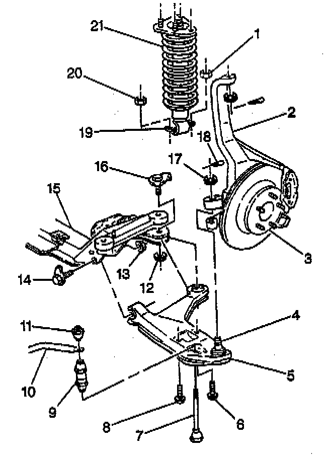
REMOVAL PROCEDURE
1. Raise and suitably support the vehicle.
2. Remove the special security wheel lock nut, if equipped. Use the special security wheel lock key which is located in the front floor console.
3. Remove the tire and the wheel.
4. Remove the power steering gear from the steering knuckle.
5. Remove the stabilizer shaft link (7). Refer to STABILIZER LINK REPLACEMENT.
6. Remove the shock absorber (19) and spring (21) from the lower control arm (5).
7. Separate the lower control arm bail stud (4) from the steering knuckle (2). Refer to LOWER BALL JOINT REPLACEMENT.
8. Remove the lower control arm from the steering knuckle.
9. Remove the bolts/screws and nuts.
10. Remove the lower control arm.
INSTALLATION PROCEDURE
1. Position the lower control arm (5) to the crossmember (15).
NOTICE: Always use the correct fastener in the proper location. When you replace a fastener, use ONLY the exact part number for that application. The manufacturer will call out those fasteners that require a replacement after removal. The manufacturer will also call out the fasteners that require thread lockers or thread sealant. UNLESS OTHERWISE SPECIFIED, do not use supplemental coatings (paints, greases, or other corrosion inhibitors) on threaded fasteners or fastener joint interfaces. Generally, such coatings adversely affect the fastener torque and joint clamping force, and may damage the fastener. When you install fasteners, use the correct tightening sequence and specifications. Following these instructions can help you avoid damage to parts and systems.
2. Hand tighten the bolts/screws and nuts.
Tighten
^ Tighten the nuts (12) to 115 Nm (85 ft. lbs.).
^ Tighten the nuts (13) to 100 Nm (74 ft. lbs.).
3. Position the lower control arm to the steering knuckle (2).
Important: Tighten the nut enough in order to align the slot with the stud hole. Never loosen the nut in order to align the slot with the hole.
4. Hand start the nut.
Tighten
Tighten the nut (17) to 110 Nm (81 ft. lbs.).
5. Install the cotter pin (18).
6. Install the lower control arm to the absorber (19) and spring (21).
7. Install the stabilizer shaft link (7). Refer to STABILIZER LINK REPLACEMENT.
8. Install the power steering gear to the steering knuckle.
9. Install the tire and the wheel.
10. Install the special security wheel lock nut, if equipped. Use the special security wheel lock key which is located in the front floor console.
11. Lower the vehicle.
12. Perform a wheel alignment.