P0121
Diagnostic Chart:
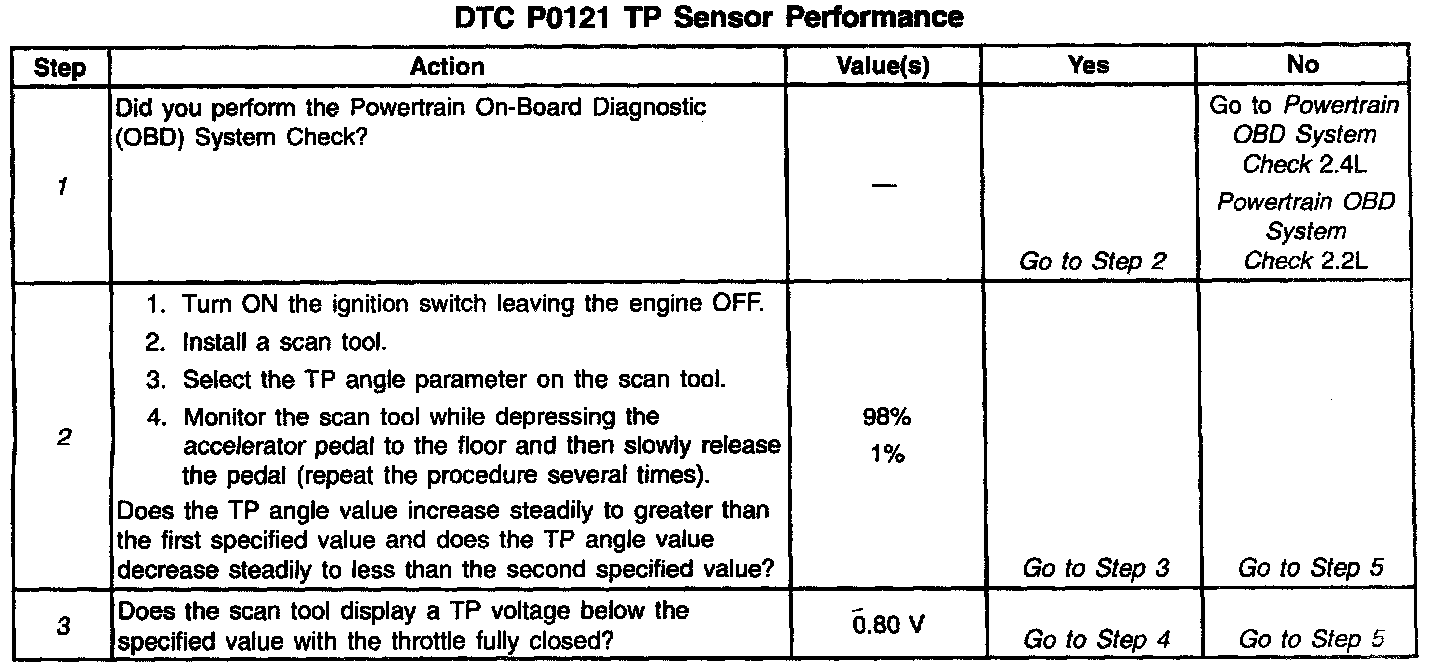
Diagnostic Chart:
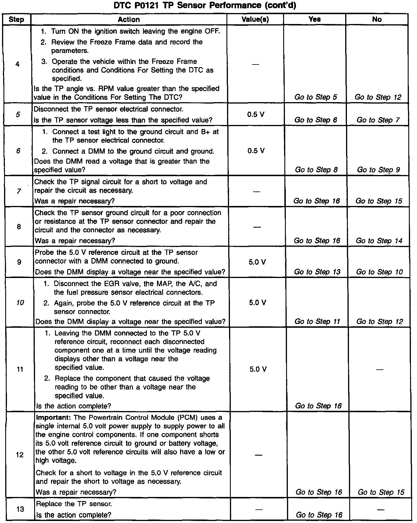
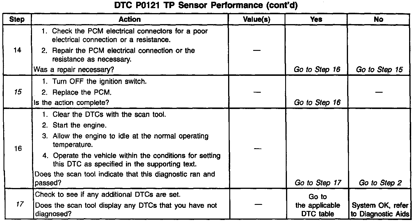
Diagnostic Chart:
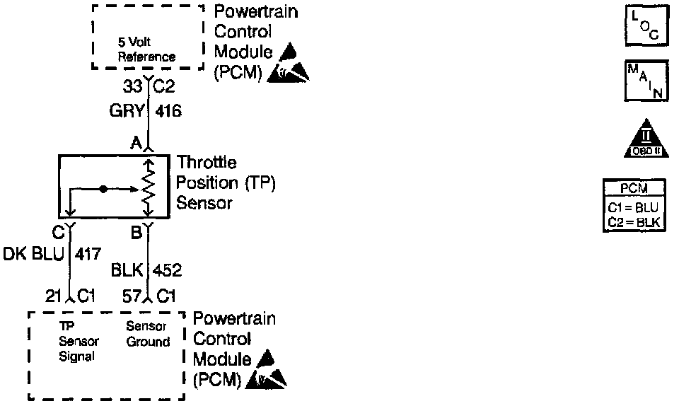
Wiring Diagram:
CIRCUIT DESCRIPTION
The PCM supplies a 5.0 V reference signal and a ground to the Throttle Position (TP) sensor. The TP sensor sends a voltage signal back to the PCM relative to the throttle plate opening. The voltage signal will vary from approximately 0.35 V at closed throttle, to over 4.65 V at wide open throttle. The PCM can detect if the TP sensor is out of the above range while cruising by waiting for a Manifold Air Pressure (MAP) change and then checks if the TP sensor has also changed as expected by calculating what the TP signal should be at a given RPM and engine load. During idle conditions, the PCM verifies that the engine is stable and at idle, and ensures that the TP signal is below a given percent.
CONDITIONS FOR SETTING THE DTC
DTC(s) P0106, P0107, P0108, P0171, P0172, P0200, P0300, P0301, P0302, P0303, P0304, P0325, P0335, P0341, P0342, P0404, P0405, P0440, P0442, P0452, P0453, P0502, P0506, P0507, P0601, P0602, P1441 not set.
TP angle is greater than 7% at idle after attempting to auto-zero.
^ Engine run time is greater than 20 seconds.
^ Engine Coolant Temperature (ECT) is greater than 20°C (68°F).
^ TP is stable ± 2%.
^ MAP is less than 30 kPa. (Manual)
^ MAP is less than 45 kPa. (Automatic)
And TP angle is greater than the following specified percentages at the given RPMs for at least 6 seconds.
^ TP angle is greater than 2% at 0 RPM
^ TP angle is greater than 10% at 800 RPM
^ TP angle is greater than 20% at 1,600 RPM
^ TP angle is greater than 25% at 2,400 RPM
^ TP angle is greater than 30% at 3,200 RPM
^ TP angle is greater than 35% at 4,000 RPM
^ TP angle is greater than 35% at 4,800 RPM
^ TP angle is greater than 40% at 5,600 RPM
^ TP angle is greater than 40% at 6,400 RPM
ACTION TAKEN WHEN THE DTC SETS
^ The Malfunction Indicator Lamp (MIL) will illuminate after two consecutive ignition cycles in which the diagnostic runs with the fault active.
^ The PCM will record the operating conditions at the time that the diagnostic fails. This information stores in the Freeze Frame and Failure Records buffers.
^ A history DTC stores.
^ The coolant fan turns ON.
CONDITIONS FOR CLEARING THE MIL/DTC
^ The MIL will turn OFF after three consecutive ignition cycles in which the diagnostic runs without a fault.
^ A history DTC will clear after 40 consecutive warm up cycles without a fault.
^ The MIL/DTC(s) can be cleared by using the scan tool.
DIAGNOSTIC AIDS
^ A TP sensor that is stuck will attempt an auto zero every time that the engine runs. The ATP sensor will not display as high a percentage as the sensor normally when the sensor has auto zeroed at a higher than normal voltage.
^ A normal TP sensor that displays 0 percent will not display higher than 1V and is possibly stuck.
^ If a DTC P0121 cannot be duplicated, the information included in the Freeze Frame/Failure Records data can be useful. Use the scan tool DTC information data in order to determine the status of the DTC.
^ A DTC P01 21 may set while attempting to start a vehicle that has run out of fuel.
TEST DESCRIPTION
The number(s) below refer(s) to the step number(s) on the Diagnostic Table.
1. The Powertrain OBD System Check prompts you to complete some of the basic checks and to store the freeze frame and failure records data on the scan tool if applicable. This creates an electronic copy of the data captured when the malfunction occurred. The scan tool stores this data for later reference.
2. The TP sensor has an auto zeroing feature. If the voltage reading is between 0.2 to 0.9 volts, the PCM will assume that the TP sensor is at a closed throttle position (0 percent). If the reading is out of the auto zeroing range at closed throttle, look for a binding or a damaged linkage.
3. The normal TP voltage is near 0.50 V when the throttle plates are fully closed. A sensor will display a higher voltage when the sensor is stuck or when a circuit is malfunctioning.
5. A disconnected TP sensor should not display a voltage reading on the scan tool. An amount less than the specified value is normal.
6. When you connect the test light to the ground circuit, the light should glow brightly if the ground circuit may be OK, but the light could have a small amount of resistance in the circuit. The DMM detects the small amounts of resistance by using the voltage drop method. If the test light glows dimly or not at all, then this indicates that the resistance in the circuit is present and using the DMM is not necessary.
7. In order for DTC P0121 to set with a short voltage in the TP signal circuit, the voltage must be minimal enough to not set a DTC P0123, and more than 0.5 V.
10. Disconnecting the EGR valve and sensors connected to the 5.0 V reference circuits internally to the PCM determines if the 5.0 V reference circuit is shorted or if one of the sensors is causing a short on the 5.0 V reference circuit.
15. Reprogram the replacement PCM and perform the crankshaft position system variation learning procedure. Refer to the latest Techline information for PCM programming and the CKP System Variation Learn Procedure for the Crankshaft Position system variation learning procedure.
17. If no malfunctions have been found at this point and no additional DTCs were set, refer to the DIAGNOSTIC AIDS for additional checks and information.