Master Cylinder Replacement
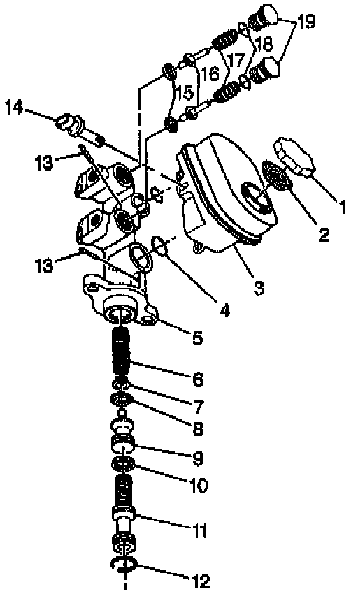
REMOVAL PROCEDURE
1. Disconnect the battery.
CAUTION: Before removing or installing any electrical unit or when a tool or equipment could easily come in contact with "live" exposed electrical terminals, disconnect the negative battery cable to help prevent personal injury and/or damage to the vehicle or components. Unless instructed otherwise, the ignition switch must be in the "OFF" or "LOCK" position.
2. Remove the air box. Refer to Air Cleaner Assembly Replacement.
3. Perform the gear tension release procedure. Refer to Antilock Brake System (ABS) and Enhanced Traction System (ETS).
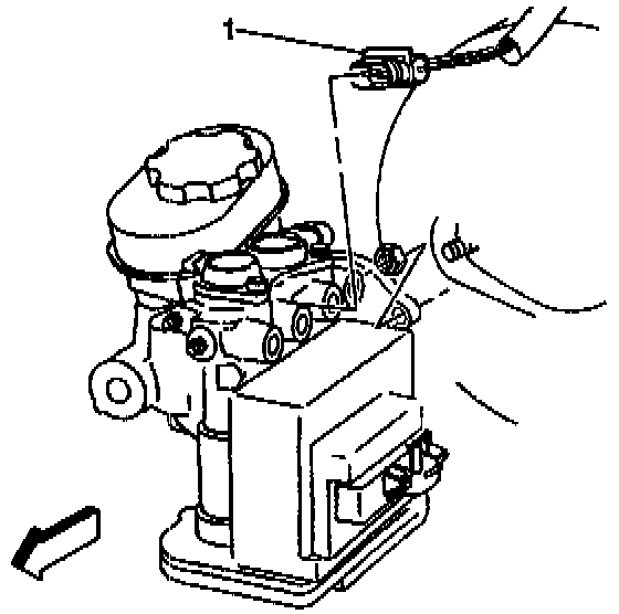
4. Disconnect the electrical connector from the fluid level switch (1).
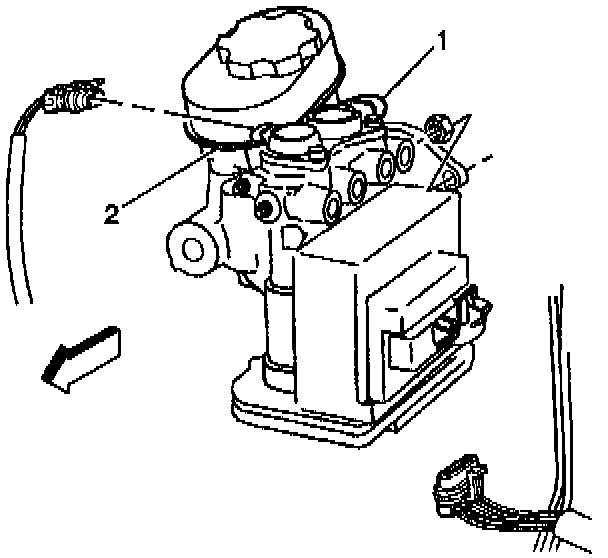
5. Disconnect the electrical connectors from both of the ABS solenoids (1,2).
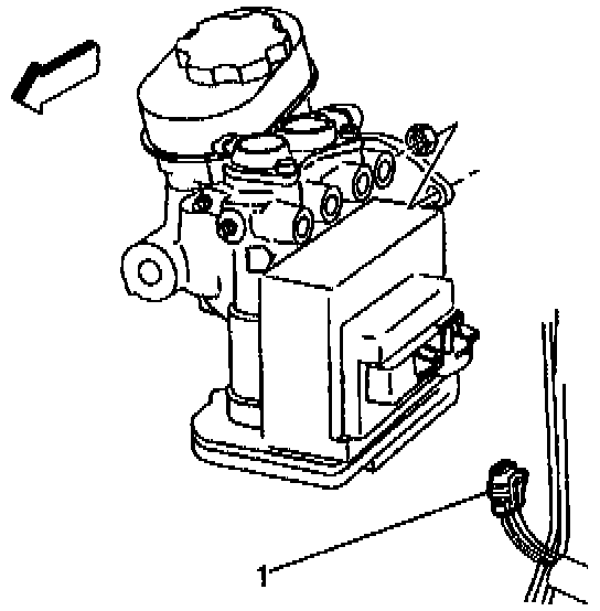
6. Remove the motor pack electrical connector (1).
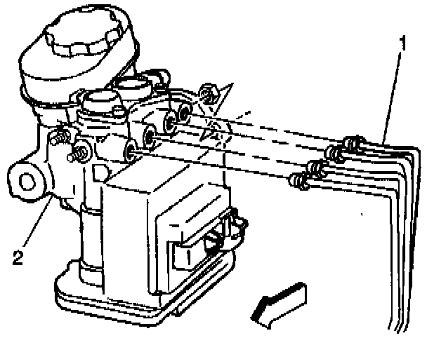
7. Disconnect the brake pipe tube nuts (1) from the master cylinder and the modulator assembly (2).
8. Plug the open brake pipes (1 ) in order to prevent brake fluid loss and contamination.
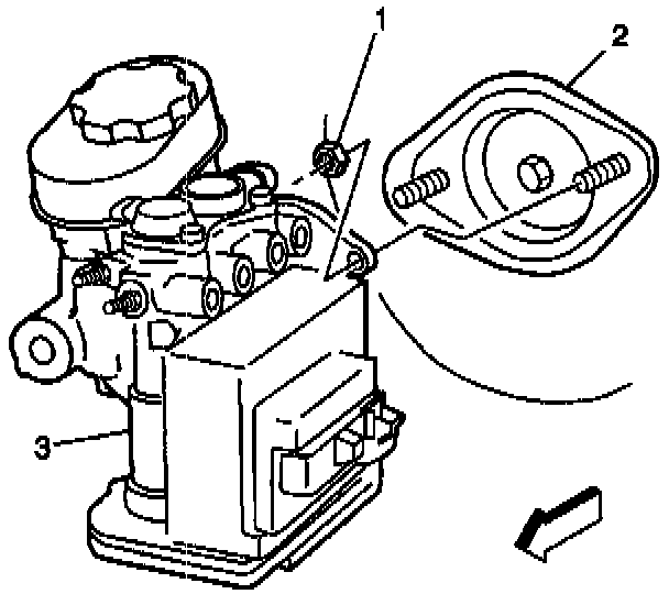
9. Remove the master cylinder mounting nuts (3).
10. Remove the master cylinder (3) from the booster (2).
INSTALLATION PROCEDURE
NOTICE: Always use the correct fastener in the proper location. When you replace a fastener, use ONLY the exact part number for that application. The manufacturer will call out those fasteners that require a replacement after removal. The manufacturer will also call out the fasteners that require thread lockers or thread sealant. UNLESS OTHERWISE SPECIFIED, do not use supplemental coatings (paints, greases, or other corrosion inhibitors) on threaded fasteners or fastener joint interfaces. Generally, such coatings adversely affect the fastener torque and joint clamping force, and may damage the fastener. When you install fasteners, use the correct tightening sequence and specifications. Following these instructions can help you avoid damage to parts and systems.
1. Install the master cylinder (3) to the booster assembly (2).
^ Tighten the master cylinder and the modulator assembly mounting nuts to 27 Nm (20 ft. lbs.).
2. Install the brake pipe tube nuts (1) to the master cylinder and the modulator assembly (2).
^ Tighten the brake pipe tube nuts to 23 Nm (17 ft. lbs.).
3. Connect the electrical connector to the fluid level switch (1).
4. Connect the electrical connectors to both solenoids (1,2).
5. Connect the motor pack electrical connectors (1).
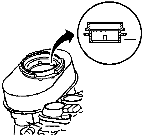
6. Fill the master cylinder to the proper level with clean brake fluid.
7. Bleed the hydraulic system. Refer to Brake Bleeding.