Removal Procedure
^ Tools Required:- J 33432-A Transverse Leaf Spring Compressor
- J 42188 Ball Joint Separator
- J 41803 Engine Support Fixture
- J 28467-B Universal Engine Support Fixture
CAUTION: Before removing or installing any electrical unit or when a tool or equipment could easily come in contact with "live" exposed electrical terminals, disconnect the negative battery cable to help prevent personal injury and/or damage to the vehicle or components. Unless instructed otherwise, the ignition switch must be in the "OFF" or "LOCK" position.
1. Disconnect the negative battery cable.
2. Remove the generator from the accessory mounting bracket. Refer to GENERATOR REPLACEMENT (COMPLETE) in POWERTRAIN MANAGEMENT.
3. Install J 41803 and J 28467-B and support the engine.
4. Raise and support the vehicle.
5. Remove the tire and wheel assemblies. Refer to TIRE AND WHEEL REMOVAL AND INSTALLATION in TIRES AND WHEELS.
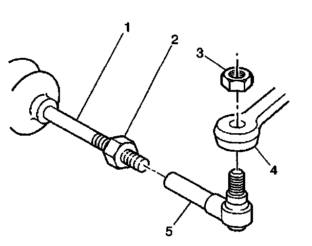
6. Loosen the steering linkage outer tie rod nuts (3). Do not remove the nuts.
7. Install J 42188 on the left steering linkage outer tie rod end.
8. Separate the left steering linkage outer tie rod (5) from the steering knuckle (4).
9. Remove J 42188 and the steering linkage tie rod nut from the left steering linkage outer tie rod.
10. Install J 42188 on the right steering linkage outer tie rod end.
11. Separate the right steering linkage outer tie rod from the steering knuckle.
12. Remove J 42188 and the steering linkage tie rod nut from the right steering linkage outer tie rod.
13. If equipped, disconnect the Real Time Dampening (RTD) sensors.
14. Support the lower control arms with jack stands.
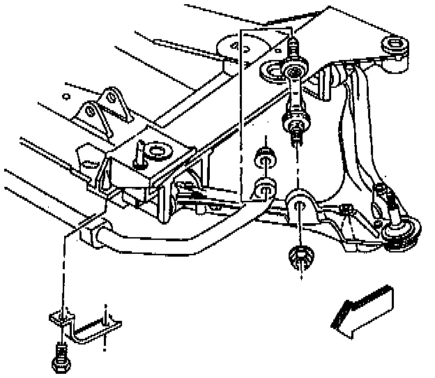
15. Disconnect the stabilizer bar links from the lower control arms.
16. Remove the stabilizer bar from the vehicle. Refer to STABILIZER SHAFT REPLACEMENT.
17. Disconnect the [1][2]intermediate shaft lower coupling from the steering gear. Refer to INTERMEDIATE STEERING SHAFT REPLACEMENT in STEERING WHEEL AND COLUMN-TILT.
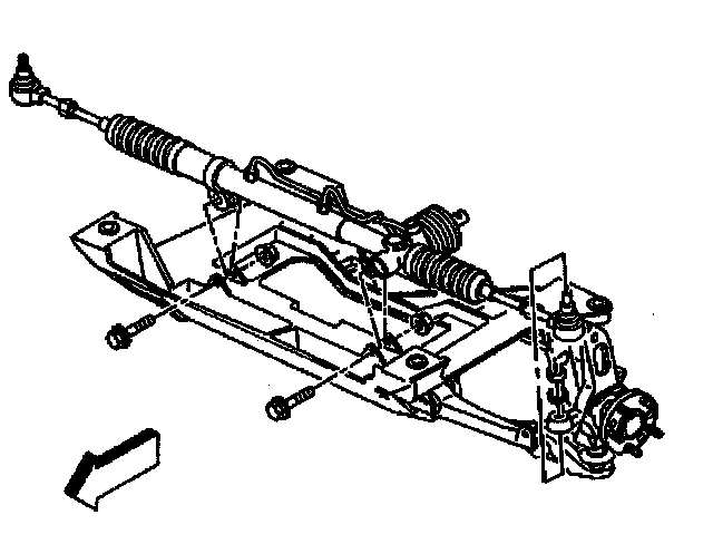
18. Remove the bolts from the brake pressure modulator valve bracket, if equipped.
19. Reposition the electronic brake control module/brake pressure modulator valve (EBTCM/BPMV) and bracket away from the crossmember, if equipped.
20. Remove the power steering gear mounting bolts.
21. Disconnect the power steering fluid cooler from the crossmember.
22. Lift the power steering gear off of the crossmember and support.
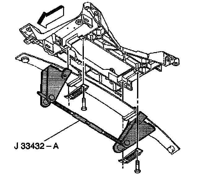
23. Install the transverse leaf spring compressor J 33432-A.
24. Compress the transverse leaf spring.
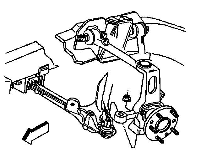
25. Loosen the lower arm ball joint stud nuts. Do not remove the nuts.
26. Install J 42188 on the lower right ball joint.
27. Separate the ball joint stud from the steering knuckle.
28. Remove the J 42188 and the ball joint stud nut.
29. Install J 42188 on the lower left ball joint.
30. Separate the ball joint stud from the steering knuckle.
31. Remove the J 42188 and the ball joint stud nut.
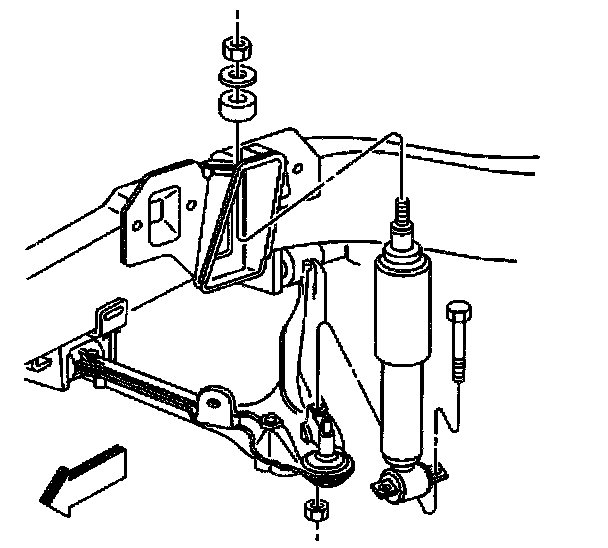
32. Disconnect the lower shock absorber bolts from the lower control arms.
33. Disconnect the lower control arms from the steering knuckles.
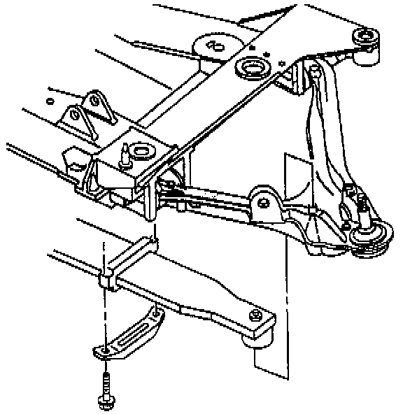
34. Remove the left transverse spring mounting bracket.
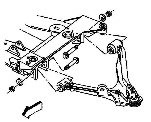
35. Remove the lower left control arm from the vehicle.
36. Remove the right transverse spring retainer.
37. Keeping J 33432-A attached to the spring, remove the transverse spring from the vehicle.
38. Remove the lower right control arm from the crossmember if necessary.
39. Place a transmission jack under the crossmember.
40. Remove the engine mount lower nuts. Refer to ENGINE MOUNT REPLACEMENT IN ENGINE.
41. Remove the crossmember mounting nuts.
42. Disconnect the wiring harness from the crossmember.
43. Disconnect the brake pipe from the crossmember.
44. Lower the crossmember out of the vehicle.