Air Distribution System
Control of air through the system is regulated by vacuum. At various positions on the control, mode valves mix and direct cooled, heated and outside air through the air ducts. The flow of air from the heater system during the various modes of operation is as follows:^ Off - Floor outlet, forced air only.
^ Max - Instrument panel outlets recirculation air.
^ Norm, A/C - Instrument panel outlets outside air.
^ Hi/Level - Instrument panel outlets and floor outlets -outside air.
^ Vent - Instrument panel outlets, outside air, no compressor operation.
^ Heater - Floor outlets and a small amount from defroster duct.
^ Mix/Blend - Equal amounts floor and defrost.
^ Defrost - Defroster outlets and a small amount from the floor outlets. The operation of the cooling fan is controlled by the powertrain control module through the cooling fan relay.
Vacuum Lines
Vacuum lines are molded to a connector which is attached to a vacuum solenoid box on the A/C module. In case of leakage or hose collapse, it will not be necessary to replace the entire harness. Replacement can be made by cutting the hose and inserting a plastic connector.
Vacuum Tank
Vacuum Tank:
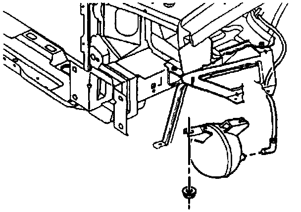
During heavy acceleration, the vacuum supply drops. A check valve in the vacuum line maintains vacuum so that, under load conditions, vacuum will be available for continuous use.
Ducts and Outlets
A system of ducts and outlets direct air to the passenger compartment. In cases of poor air output, defroster, heater, A/C and vent ducts should be checked for obstructions, such as leaves, dirt, objects, etc. A/C systems also come equipped with side window defoggers. For removal and installation of all ductwork.