Master Cylinder Replacement
REMOVAL PROCEDURE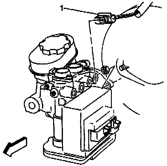
1. Remove the air cleaner assembly.
2. Perform the gear tension release procedure. Refer to Brake Modulator/Master Cylinder Assembly Replacement in Antilock Brake System.
3. Disconnect the electrical connector from the fluid level switch (1).
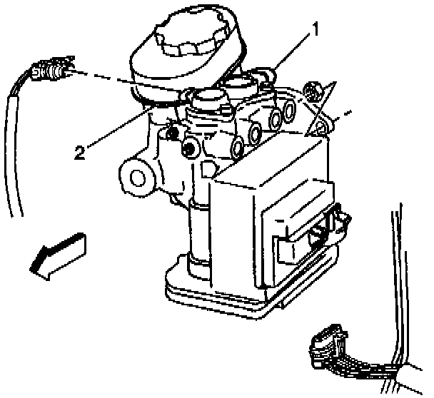
4. Disconnect the electrical connectors from both of the ABS solenoids (1,2).
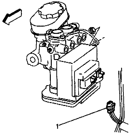
5. Remove the ABS motor pack electrical connector (1).
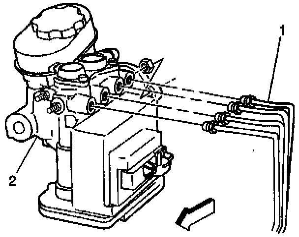
6. Disconnect the brake pipes (1) from the master cylinder and modulator assembly (2).
7. Plug the open brake pipes (1) in order to prevent brake fluid loss and contamination.
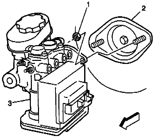
8. Remove the master cylinder mounting nuts (1).
9. Remove the master cylinder and modulator assembly (3) from the booster (2).
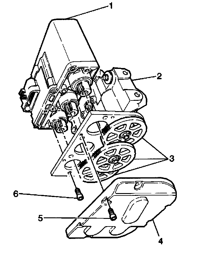
10. Remove the Torx)& head screws (5) attaching the gear cover (4).
11. Remove the gear cover (4).
12. Remove the four Torx head screws (6) attaching the motor pack (1) to the brake modulator (2).
13. Remove the motor pack (1) from the brake modulator (2).
14. Remove the two brake modulator to master cylinder banjo bolts, separate the brake modulator from the master cylinder.
15. Remove the two transfer tubes with the O-rings from the master cylinder or the brake modulator.
16. Remove the banjo bolt O-rings from the master cylinder and the brake modulator.
INSTALLATION PROCEDURE
IMPORTANT: Use new transfer tube assemblies when assembling the ABS brake modulator/master cylinder assembly. Properly install two O-rings on each transfer tube.
1. Use the following procedure in order to install the two transfer assemblies:
1.1. Lubricate the transfer tube assembly O-rings with clean brake fluid.
1.2. Install the transfer tube assemblies into ports of the ABS brake modulator. Push the tube assemblies in by hand to the bottom of the ports.
2. Lubricate the new banjo bolt O-ring with clean brake fluid.
3. Install the banjo bolt O-ring into the master cylinder and the ABS brake modulator.
4. Use the following procedure in order to install the ABS brake modulator onto the master cylinder:
4.1. Clamp the mounting flange of the master cylinder in a vise.
4.2. Hold the ABS brake modulator and rock the modulator into position on the master cylinder.
4.3. Insert the transfer tube assemblies into the master cylinder ports.
NOTICE: Refer to Fastener Notice in Service Precautions.
5. Install two ABS brake modulator to master cylinder banjo bolts.
^ Tighten the banjo bolts to 24 Nm (18 ft. lbs.).
6. With the ABS brake modulator positioned upside down, and the gears facing you, rotate each ABS brake modulator gear clockwise until movement stops. The procedure causes the following conditions:
^ The pistons are positioned very close to the top of the modulator bore.
^ The brake bleeding procedure is simplified.
7. Install the ABS brake motor pack (1) onto the brake modulator/master cylinder assembly (2).
8. Install the four Torx head screws (6) that retain the motor pack (1) to the brake modulator (2).
^ Tighten the four Torx head screws to 5 Nm (44 inch lbs.).
9. Install the gear cover (4) to the brake modulator/master cylinder assembly (2).
10. Install the Torx head screws (5) that retain the gear cover (4).
^ Tighten the Torx head screws to 4 Nm (36 inch lbs.).
NOTICE: Refer to Fastener Notice in Service Precautions.
11. Install the master cylinder and modulator assembly (3) to the booster assembly (2).
^ Tighten the master cylinder mounting nuts to 27 Nm (20 ft. lbs.).
12. Install the brake pipes (1) to the master cylinder and modulator assembly (2).
^ Tighten the brake pipe tube nuts to 23 Nm (17 ft. lbs.).
13. Connect the electrical connector to the fluid level switch (1).
14. Connect the electrical connectors to both solenoids (1,2).
15. Connect the ABS motor pack electrical connector (1).
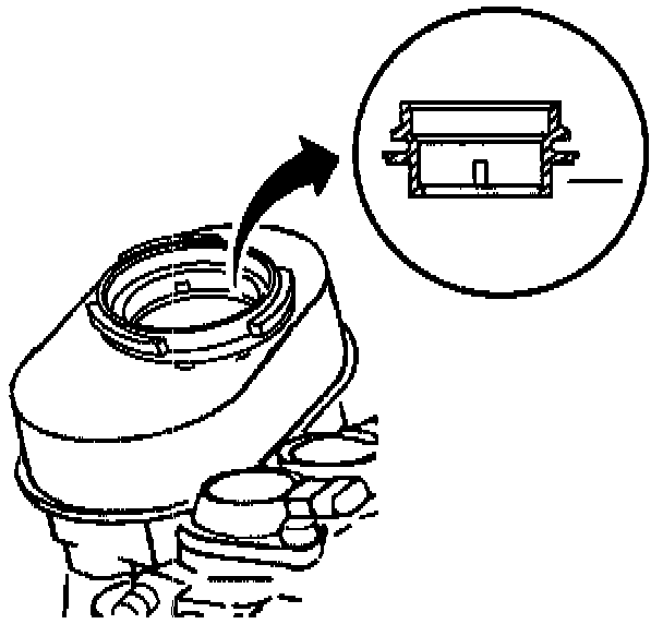
16. Fill the master cylinder to the proper level with clean brake fluid.
17. Bleed the hydraulic system.