Steps 52-102
51. Disconnect the electronic variable orifice control (EVO) connector clips from the crossmember.
52. Disconnect the real time damping (RTD) connector clips from the crossmember (if equipped).
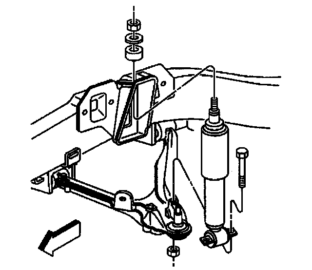
53. Remove the shock-absorber lower mounting bolts.
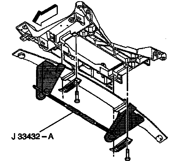
54. Remove the front transverse leaf spring. Refer to Front Transverse Spring Replacement in Steering and Suspension.
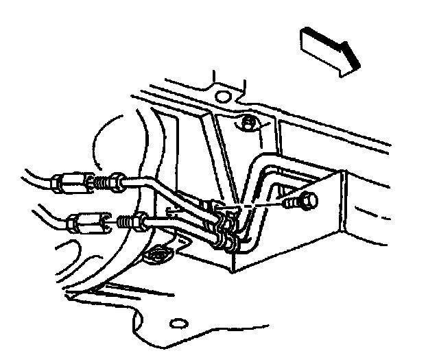
55. Disconnect the automatic transmission cooler pipes at the engine flywheel housing junction (if equipped).
56. Disconnect the automatic transmission cooler pipe clamps from the front and the rear of the engine oil pan (if equipped).
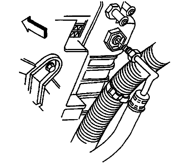
57. Disconnect the automatic transmission cooler pipes from the radiator (if equipped).
Notice: Refer to Fastener Notice in Service Precautions.
Important: Failure to use the minimum fastener length specified will prevent proper retention of the propeller shaft during disassembly.
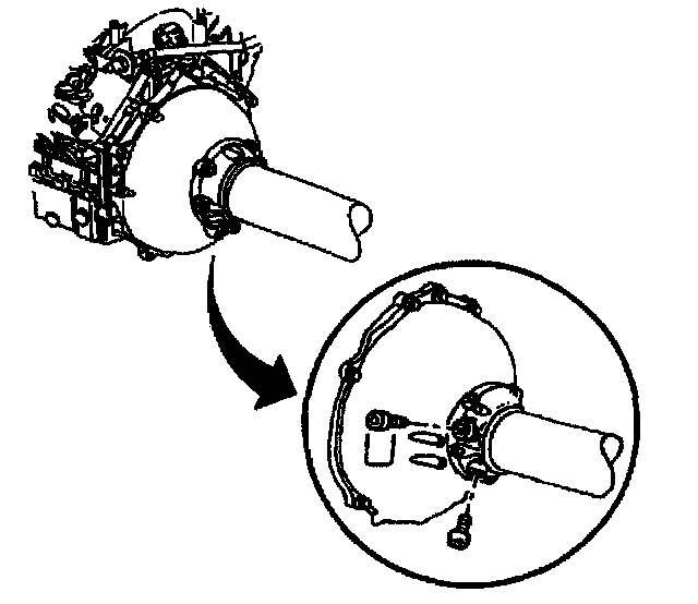
58. With automatic transmission vehicles, use the following steps:
58.1. Remove the two plug bolts in the driveline support assembly.
58.2. Install a M10.0-1.5 x 55 mm bolt or longer in each plug location.
Tighten
Tighten the M10 bearing support bolts to 35 Nm (26 ft. lbs.).
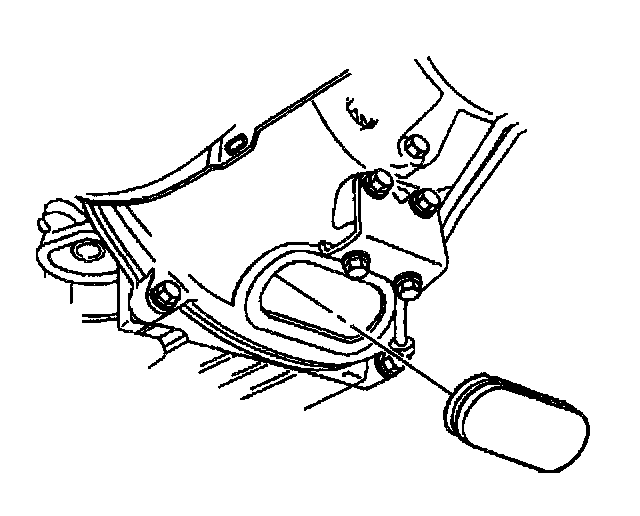
59. With automatic transmission vehicles, remove the engine flywheel housing access plug.
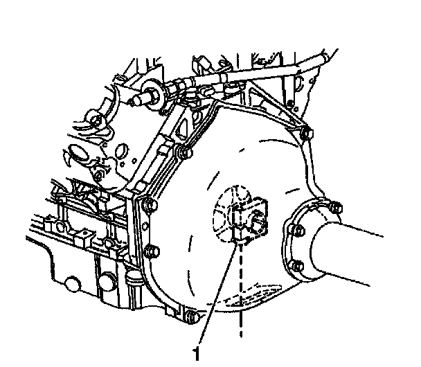
60. Orientate the automatic transmission flywheel hub collar to access the bolt (1).
61. Position the collar bolt facing downward.
62. Loosen the automatic transmission flywheel hub collar bolt (1).
63. Unclip the wiring harness from engine and reposition it to the driveline.
Important: The weight of the engine should never be supported by J 42203.
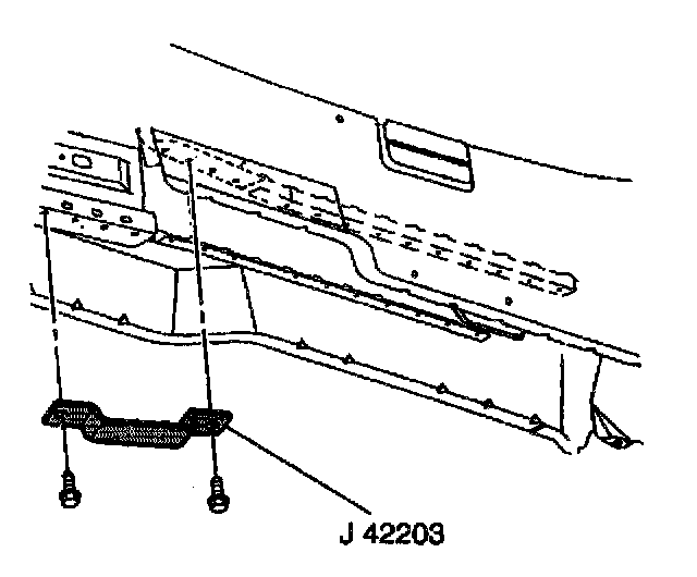
64. Install J 42203 to the close-out panel flange.
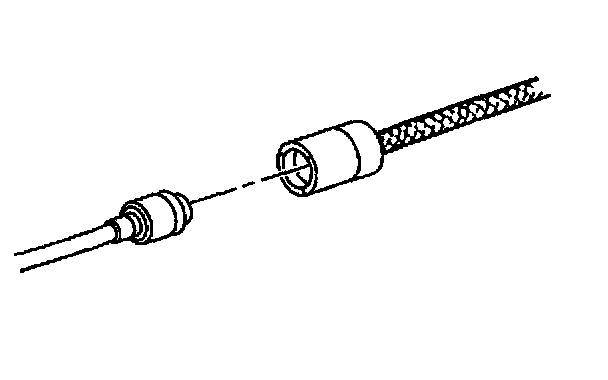
65. Vehicles equipped with a manual transmission need to:
65.1. Unclip the clutch actuator hose from the engine flywheel housing clip.
65.2. Using J 36221, depress the white circular release ring on the actuator hose and simultaneously pull lightly on the master cylinder hose to disconnect.
65.3. Protect both ends from dirt and damage.
65.4. Remove the engine flywheel housing bolts from the driveline support assembly.
Important: The weight of the engine should never be supported by J 42203.
66. Install J 42203 to the close- ' out panel flange.
67. Slowly lower the vehicle to the J 39580 and J 39580-500.
68. Support the engine and crossmember assembly on J 39580 and J 39580-500.
69. BY HAND, remove the front and rear crossmember nuts.
70. Partially raise the vehicle.
71. Remove the AIR tube bracket bolt and reposition the tube bracket to gain access to the left rear ground strap.
72. Remove the ground strap from the rear of left cylinder head.
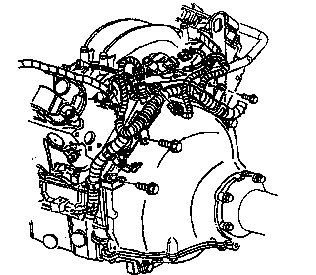
73. Disconnect the following electrical connectors from the back of the engine:
- The engine oil pressure sensor
- The camshaft position sensor
- The manifold absolute pressure (MAP) sensor
- The knock sensor wire harness connector
- All remaining electrical connections
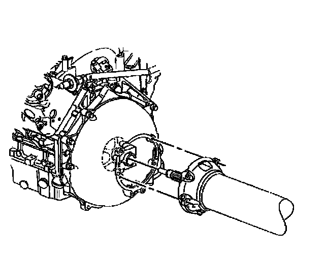
74. Remove the front driveline support assembly bolts from the driveline.
Important: Visually inspect the wiring harness detachment from the engine.
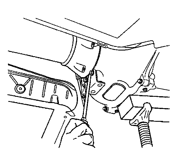
75. Insert a flat bladed screwdriver, or similar tool, between the edge of driveline support assembly and the engine flywheel housing, then pry the engine loose from the driveline.
76. Slowly pull the engine away from the propeller shaft.
77. As soon as the propeller input shaft clears the engine flywheel housing, slowly raise the vehicle.
78. Slide the engine and crossmember assembly forward in order to clear the propeller shaft spline.
Important: Visually inspect the wiring harness clearances while raising the vehicle.
79. Raise the vehicle completely off of the engine and crossmember assembly.
Important: It is not necessary to open the power steering system during the engine removal procedure.
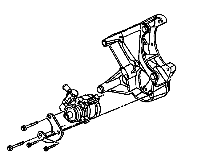
80. Remove the power steering pump pulley using J25034-C.
81. Remove the power steering pump bolts.
82. Remove the power steering pump and reservoir from the engine and reposition them to the crossmember.
83. Remove the air conditioning (AC) compressor belt.
84. Remove the air conditioning compressor bolts and nut. Refer to Compressor Replacement in Heating and Air Conditioning.
85. Remove the air conditioning compressor stud and compressor from the engine.
86. Remove the air conditioning compressor bracket bolt and bracket.
87. Remove the AIR tube mounting bolts and tube from the exhaust manifolds.
88. Install J 41798 to the engine.
89. Install a lifting device to the J 41798.
90. Remove the spark plug wires from the spark plugs.
91. Remove the spark plugs from the cylinder heads. Refer to Spark Plug Replacement in Powertrain Management.
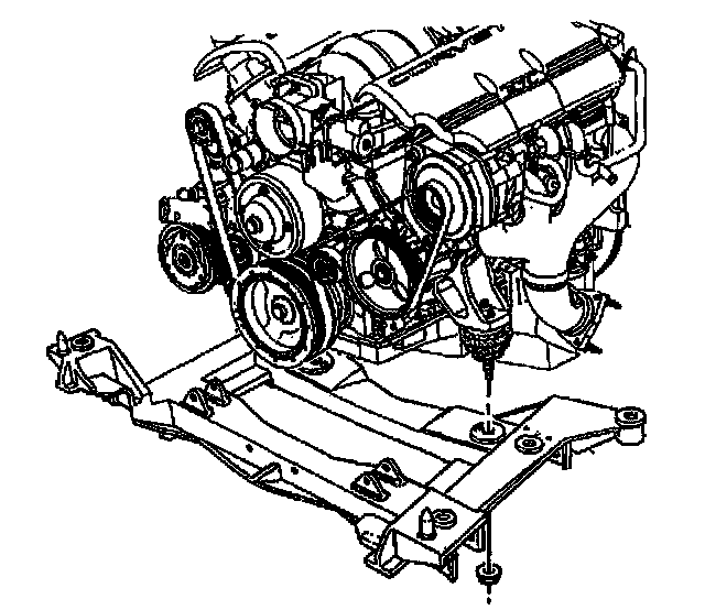
92. Remove the engine mount to crossmember nuts.
93. Remove the engine from the crossmember, using J 41798.
94. Remove the J 41798 from the engine.
Installation Procedure
Important The steps in the following procedure are in a specific order. Follow these steps in this order and ignore no details.
1. Install J 41798 to the engine.
2. Install a lifting device to the J 41798.
3. Install the engine to the crossmember.
Notice: Refer to Fastener Notice in Service Precautions.
4. Install the crossmember nuts to the engine mount.
Tighten the engine mount nuts to 54 Nm (40 ft. lbs.).
5. Install the spark plugs to the cylinder heads. Refer to Spark Plug Replacement in Powertrain Management.
6. Install the spark plug wires to the spark plugs.
7. Install the AIR pipe and mounting bolts to the exhaust manifolds.
Tighten the AIR pipe to 20 Nm (15 ft. lbs.).
8. Install the AC compressor bracket and bolt to the engine.
Tighten the AC compressor bracket bolts to 50 Nm (37 ft. lbs.).
9. Install the AC compressor mounting stud to the engine.
Tighten the AC compressor mounting stud to 9 Nm (80 in ft.).
10. Install the AC compressor to the AC bracket. Refer to Compressor Replacement in Heating and Air Conditioning.
11. Install the AC compressor belt. Refer to Drive Belt Replacement - A/C.
12. Install the power steering pump and reservoir to the engine.
13. Install the power steering pump mounting bolts.
Tighten the power steering pump mounting bolts to 25 Nm (18 ft. lbs.).
14. Install the power steering pump pulley to the pump using J25033-C.
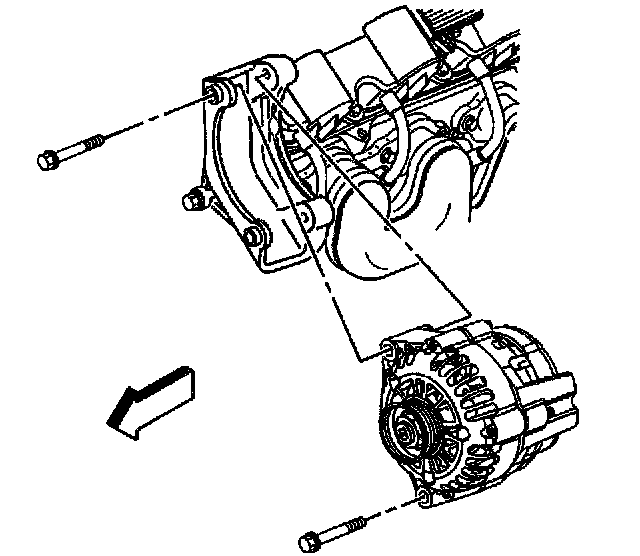
15. From the new engine, remove the generator mounting bolts.
16. Remove the generator.
17. Remove the generator mounting bracket bolt and bracket.
18. Roll the engine and crossmember assembly underneath the vehicle.
19. Partially lower the vehicle to the engine and crossmember assembly.
20. Install the ground strap to the rear of the left cylinder head.
Tighten the ground strap bolt to 32 Nm (24 ft. lbs.).
21. Install the AIR tube bracket bolt and the bracket.
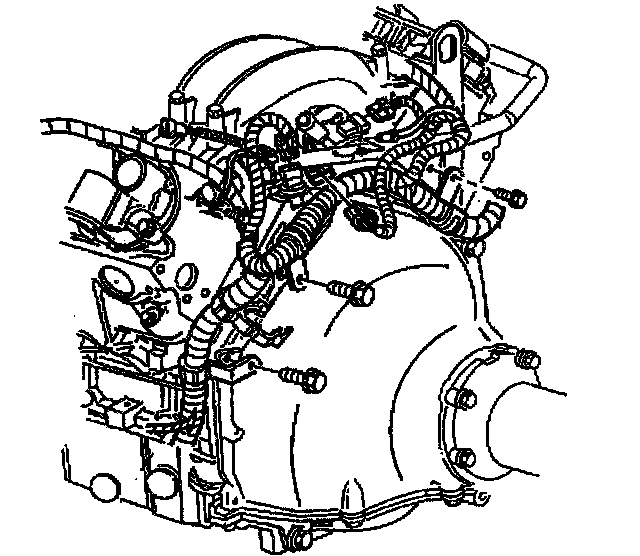
22. Route the electrical harnesses and connect the following electrical connectors at the rear of the engine:
- The engine oil pressure sensor
- The camshaft position sensor
- The MAP sensor
- The knock sensor wire harness connector
- All remaining electrical connections at the rear of the engine
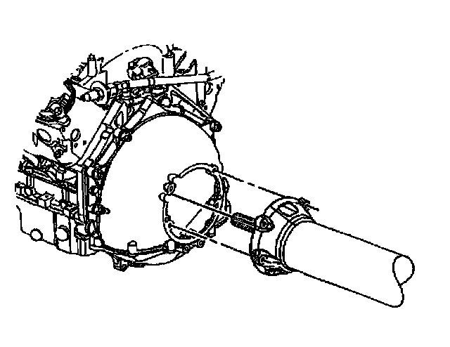
23. Vehicles equipped with a manual transmission, slide the engine and crossmember assembly rearward. Do not force the engine onto the propeller spline.
24. Position the engine to the proper height and angle in order to install the propeller input shaft.
25. Insert the propeller input shaft into the clutch driven plate hub while maintaining the proper angle, Do Not Force. Rotate the shaft slightly to bring the two splines Into alignment, if necessary.
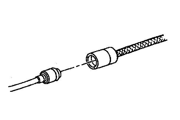
26. Slowly seat the engine flywheel housing to the driveline.
27. Install the front driveline support bolts.
Tighten the engine flywheel housing to the driveline support assembly bolts to 50 Nm (37 ft. lbs.).
28. Clip the clutch actuator hose to the engine flywheel housing clip.
29. Connect the master cylinder hose to the clutch actuator hose.
Important: Do not tighten the flywheel hub collar bolt at this time.
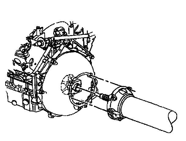
30. Vehicles equipped with an automatic transmission, slide the engine and crossmember assembly rearward. Do not force the engine onto the propeller spline.
31. Position the engine to the proper height and angle in order to install the propeller input shaft.
32. Install the front driveline support bolts.
Tighten the engine flywheel housing to the driveline support assembly bolts to 50 Nm (37 ft. lbs.).
33. Hand tighten the flywheel hub collar bolt.
34. Install the AIR tube bracket and mounting bolts to the left cylinder head.
Tighten the AIR tube to 50 Nm (37 ft. lbs.).
35. Lower the vehicle onto the crossmember and align the dowels.
Important: Use only hand tools when tightening or torquing crossmember nuts.
36. By HAND, install now crossmember nuts.
Tighten the crossmember nuts to 110 Nm (81 ft. lbs.).
37. Raise the vehicle.
38. Clip the wiring harness to the rear of the engine.
39. Remove J 42203 from the vehicle.
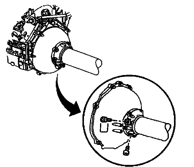
40. Vehicles equipped with an automatic transmission, remove the previously installed M10-1.5 x 55mm bolts from the front of the driveline support assembly.
41. Install two plugs in the driveline support assembly.
Tighten the plugs to 50 Nm (37 ft. lbs.).
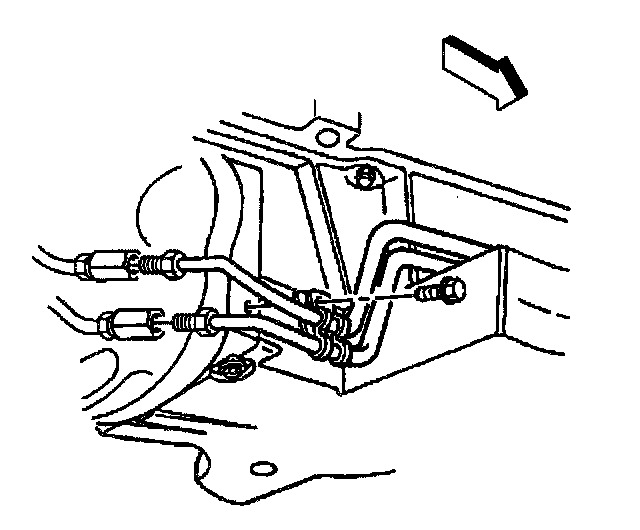
42. Connect the automatic transmission cooler pipes at the engine flywheel housing junction (if equipped).
Tighten the automatic transmission cooler pipes to 27 Nm (20 ft. lbs.).
43. Install the automatic transmission cooler pipe front retaining clamp bolt, if equipped.
Tighten the automatic transmission cooler pipe front retaining clamp bolt to 12 Nm (106 inch lbs.).
44. Install the automatic transmission cooler pipe rear retaining clamp bolt, if equipped.
Tighten the automatic transmission cooler pipe rear retaining clamp bolt to 2.5 Nm (22 inch lbs.).
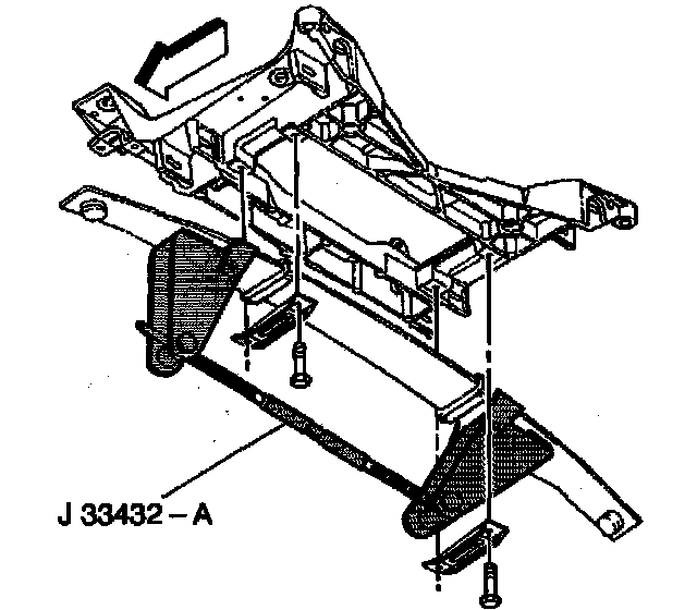
45. Install the front transverse leaf spring. Refer to Front Transverse Spring Replacement in Steering and Suspension.
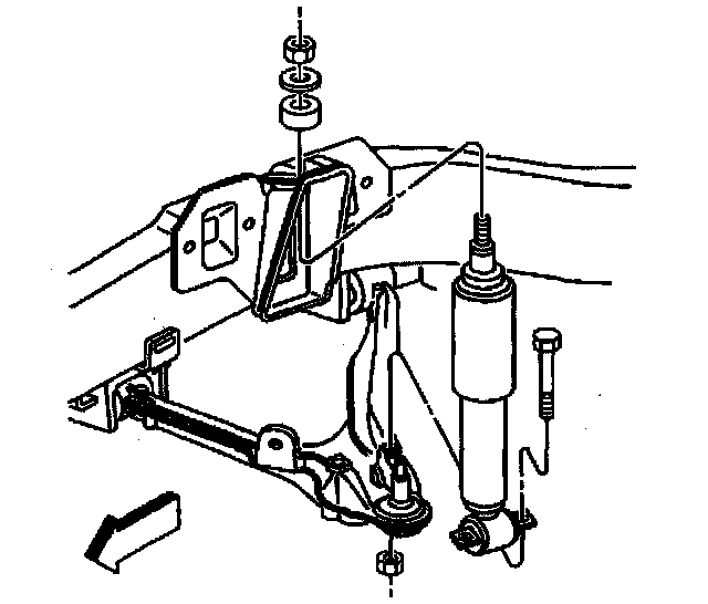
46. Install the shock absorber lower mounting bolts.
Tighten the shock absorber lower mounting bolts to 28 Nm (21 ft. lbs.).
47. Install the ABS electrical connector clips to the crossmember.
48. Install the EVO electrical connector clips to the crossmember.
49. Install RTID electrical connector clips to the crossmember (if equipped).
50. Remove J 33432-A from the spring.
51. Install the radiator. Refer to Radiator Replacement in Cooling System.
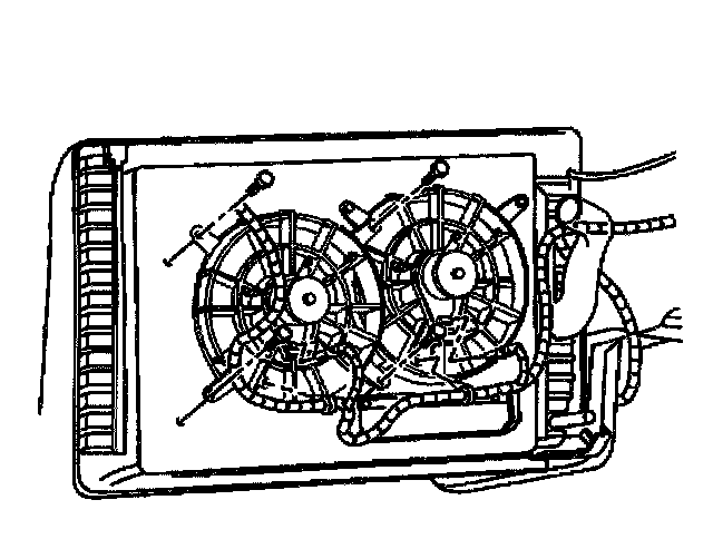
52. Install the electric cooling fan assembly to the radiator by sliding the whole unit into the slots provided.
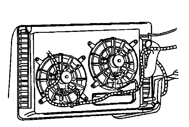
53. Connect the electrical connectors and harness to the electric cooling fans.
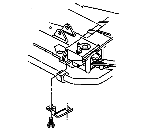
54. Install the front stabilizer shaft to the lower control arms. Refer to Stabilizer Shaft Replacement in Steering and Suspension.
55. Install the wiring harness ground wires to the left side of the engine.
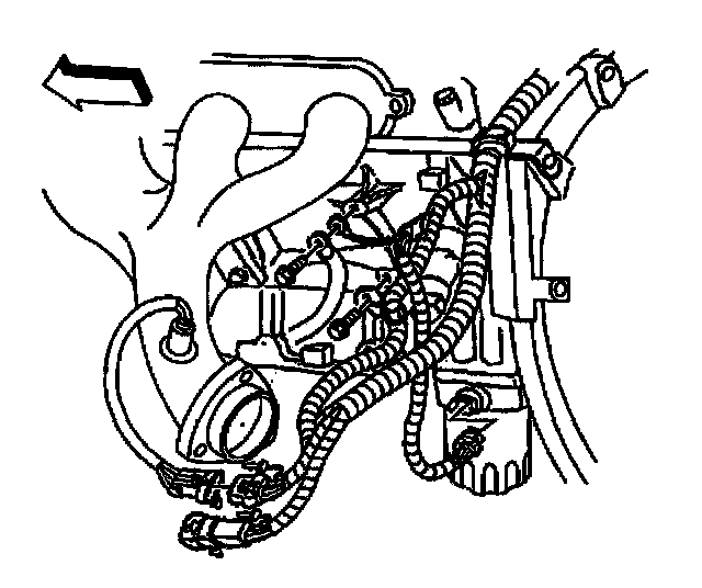
56. Connect the left front H02S sensor connector.
57. Connect the engine oil temperature sensor connector.
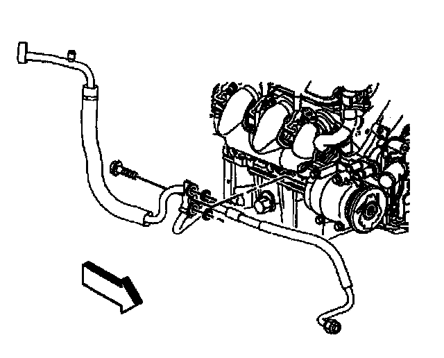
58. Install the AC compressor hose assembly to the compressor.
59. Install the AC compressor line retaining bolt.
Tighten the AC compressor hose mounting bolts to 35 Nm (26 ft. lbs.).
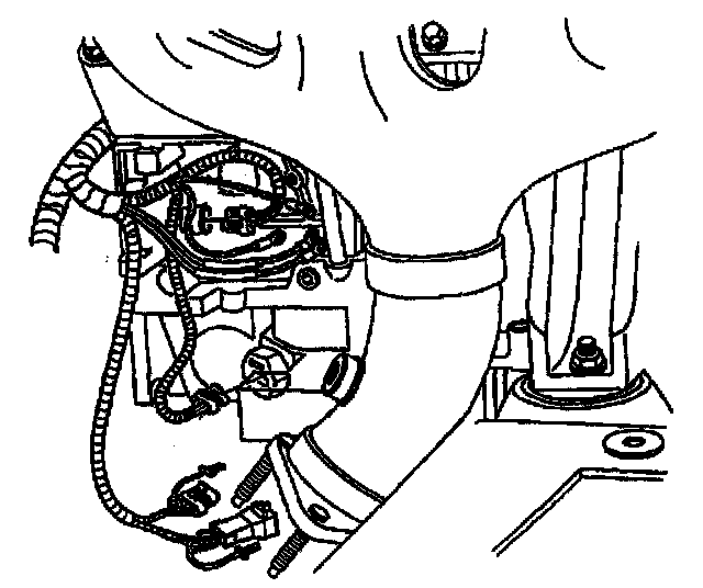
60. Connect the right front H02S sensor connector.
61. Connect the crank position sensor connector.
62. Connect the oil level sensor connector.
63. Install the wiring harness ground wires to the right side of the engine block.
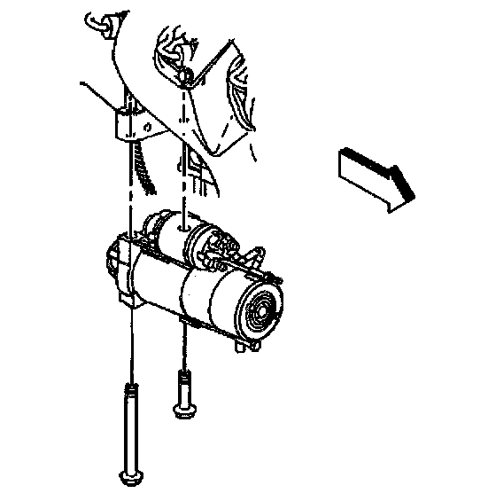
64. Install the starter. Refer to Starter Motor Replacement in Starting and Charging.
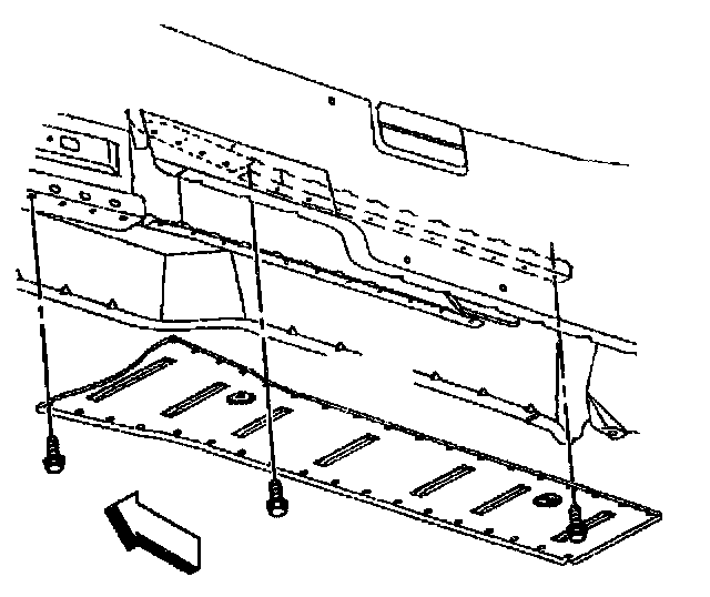
65. Install the driveline close-out panel.
66. Install the driveline close-out panel bolts.
Tighten the close-out panel bolts to 12 Nm (106 inch lbs.).
67. Install the intermediate exhaust pipe and hangers. Refer to Intermediate Pipe Replacement in Exhaust System.
68. Install the H02S sensors and clip harness.
69. Install the front tire and wheel assemblies.
Tighten the wheel nuts to 140 Nm (100 ft. lbs.).
70. Lower the vehicle.
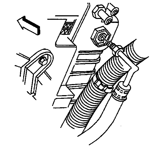
71. Connect the automatic transmission cooler pipes to the radiator (if equipped). Refer to Specifications in Transmission and Drivetrain.
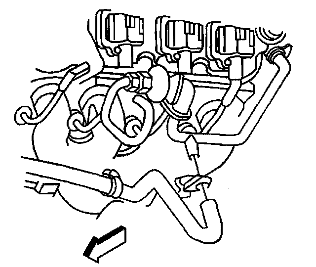
72. Connect the AIR hose to the left exhaust manifold.

73. Connect the intermediate steering shaft to the steering gear.
74. Install the intermediate steering shaft bolt.
Tighten the intermediate steering shaft bolt to 48 Nm (35 ft. lbs.).
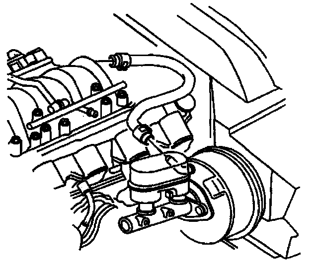
75. Connect the brake booster vacuum hose to the brake booster.
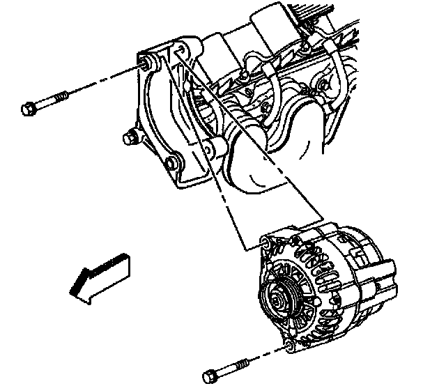
76. Install the generator mounting bracket.
77. Install the generator mounting bracket bolt.
Tighten the generator mounting bracket bolt to 50 Nm (37 ft. lbs.).
78. Install the generator.
79. Install the generator mounting bolts.
Tighten the generator mounting bolts to 50 Nm (37 ft. lbs.).
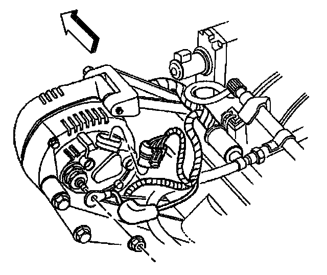
80. Connect the generator electrical connectors.
Tighten the nuts to 13 Nm (10 ft. lbs.).
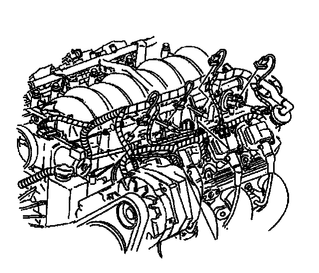
81. Connect the following electrical connectors to the top of the engine:
- The fuel injectors
- The ignition coil main connectors
- The EVAP solenoid
- The electric throttle motor
- The throttle position sensor
- The ECT sensor
- The AC compressor
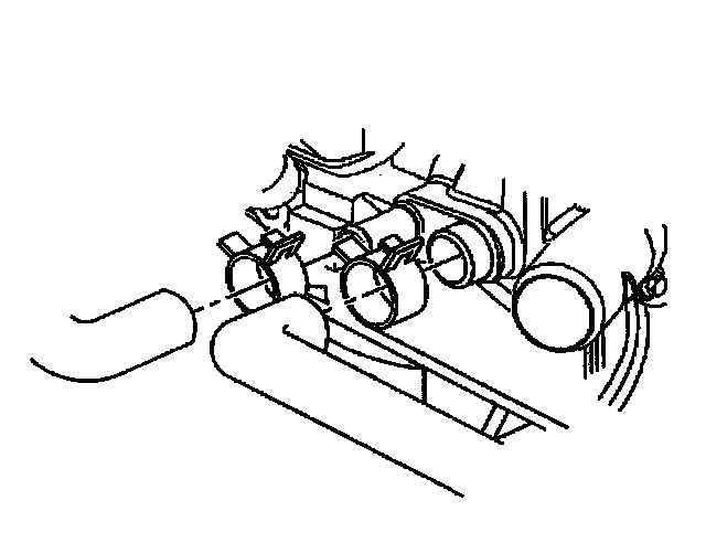
82. Connect the heater hoses to the water pump.
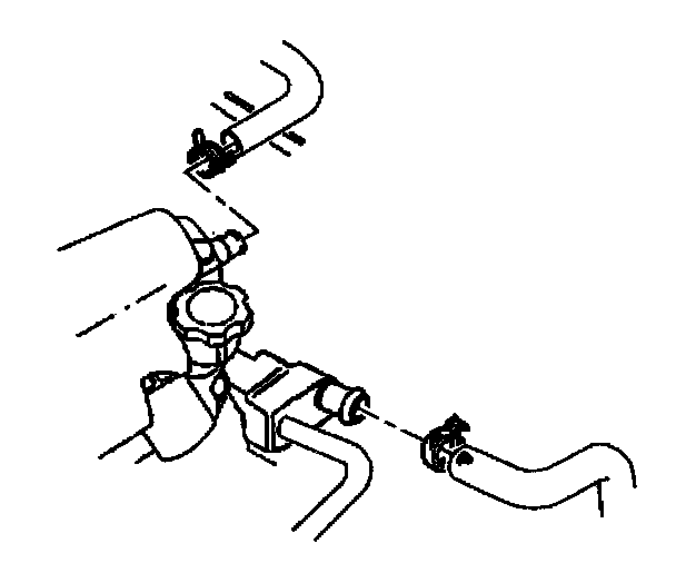
83. Connect the radiator hoses to the water pump.
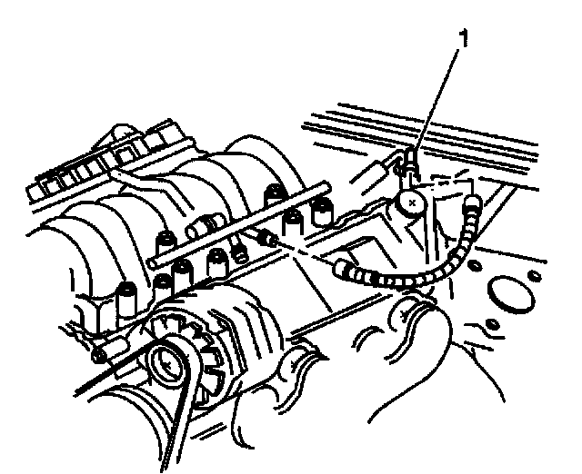
84. Connect the fuel line to the fuel rail (1).
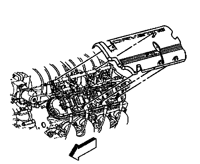
85. Install the fuel rail covers.
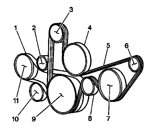
86. Install the accessory drive belt (5).
87. Install the Electronic Brake Control Module/Break Pressure Modulator Valve (EBTCM/BPMV) and bracket (1). Refer to Brake Pressure Modulator Valve (BPMV) Bracket Replacement in Brakes and Traction Control.
88. Install the top radiator hose.
89. Install the upper radiator support.
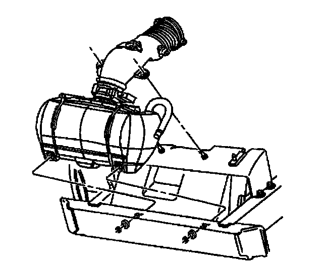
90. Reposition the air intake duct and the air cleaner assembly.
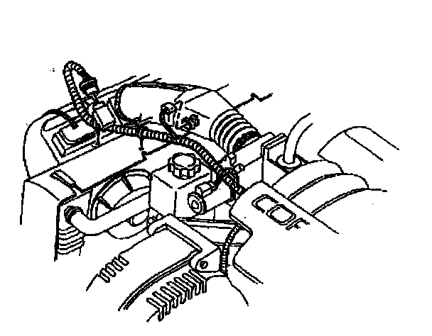
91. Connect the IAT sensor connector.
92. Connect the MAF sensor connector.
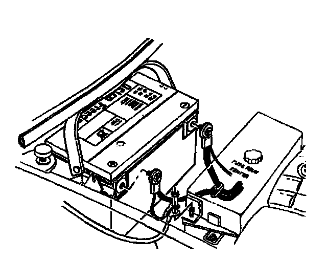
93. Connect the negative battery cable.
Tighten the negative battery cable bolt to 15 Nm (11 ft. lbs.).
94. Fill or top off the engine with oil.
95. Refill the cooling system. Refer to Draining and Filling Cooling System in Cooling System.
96. Recharge the AC system. Refer to Refrigerant Recovery and Recharging in Heating and Air Conditioning.
97. Program the Transmitters. Refer to Transmitter Programming/Synchronization in Accessories and Optional Equipment.
98. Check and fill the transmission fluid.
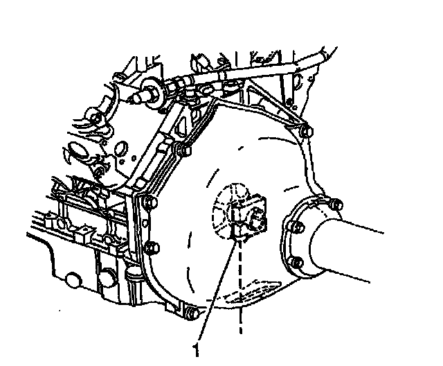
99. With automatic transmission vehicles use the following steps:
99.1. Start the engine and warm to operating temperature.
Idle for at least 10 minutes.
99.2. Shut off the engine.
99.3. Allow engine to cool to room temperature.
99.4. Raise the vehicle.
99.5. Tighten the hub collar bolt (1).
Tighten
Tighten the flywheel hub collar bolt to 130 Nm (96 ft. lbs.).
100. Install the engine flywheel housing inspection plug.
101. Check the engine for problems. Refer to Engine Set-Up and Testing.
102. Perform a wheel alignment. Refer to Measuring Wheel Alignment (Front).