Removal Procedure
Removal Procedure^ Tools Required
- J 42188 Ball Joint Separator
Notice: The Front and Rear Wheel Hub/Wheel Speed Sensors are not interchangeable. When you are replacing a Wheel Hub/Wheel Speed Sensor be sure to use the correct Wheel Hub/Wheel Speed Sensor part number. Do not mount the Rear Wheel Hub/Wheel Speed Sensor in the front steering knuckle. The Rear Wheel Hub/Wheel Speed Sensor features a splined hole through the center of the bearing which mates to the drive axle. The Rear Wheel Hub/Wheel Speed Sensor requires the support of the drive axle and the drive axle nut clamped joint to properly carry the vehicle loads. Mounting the Rear Wheel Hub/Wheel Speed Sensor in the front steering knuckle can cause bearing failure and possible damage to the vehicle.
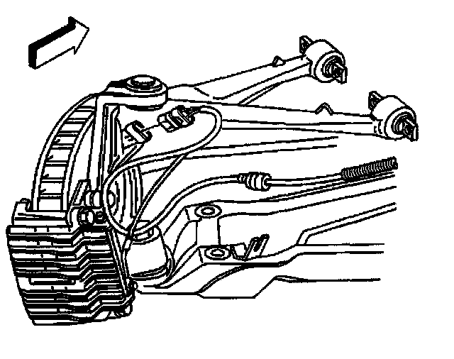
1. Raise and support the vehicle. Refer to Vehicle Lifting.
2. Remove the tire and wheel assembly.
3. Disconnect the wheel speed sensor electrical connector.
4. Remove the brake caliper and rotor.
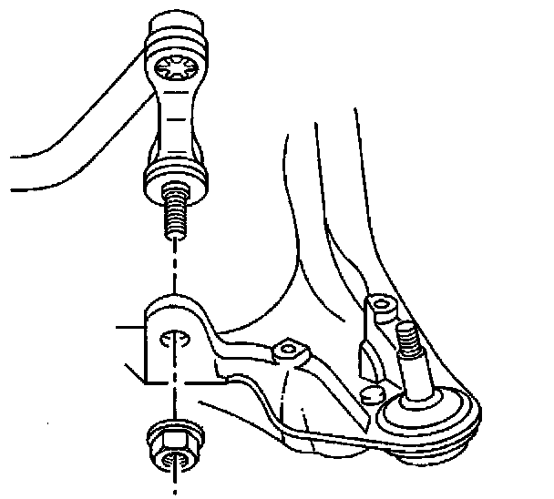
5. Remove the stabilizer shaft link from the lower control arm.
6. Support the lower control arm using a jackstand.
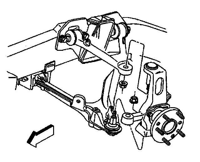
7. Separate the outer tie rod ball stud from the steering knuckle using J 42188. Refer to Tie Rod End Replacement - Outer - Off Vehicle.
8. Separate the lower ball joint stud from the steering knuckle using J 42188. Refer to Lower Control Arm Replacement.
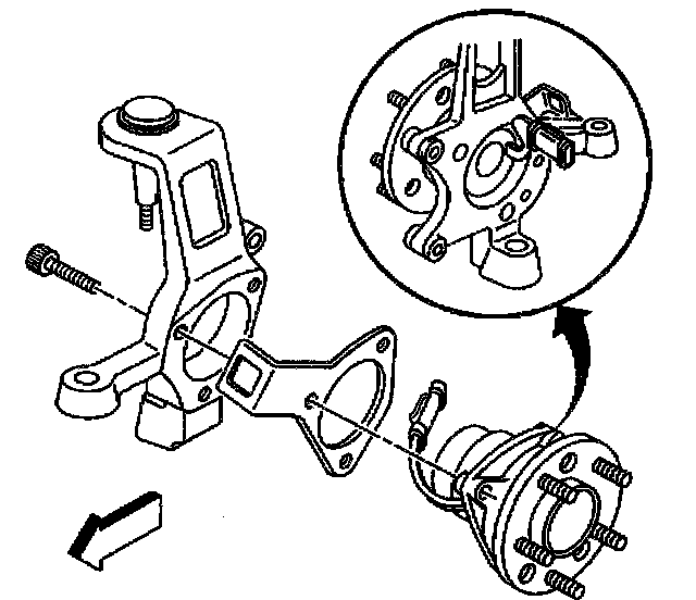
9. Remove the wheel hub mounting bolts.
10. Remove the hub and bearing assembly from the steering knuckle.