Fuel Pump Electrical Circuit Diagnosis
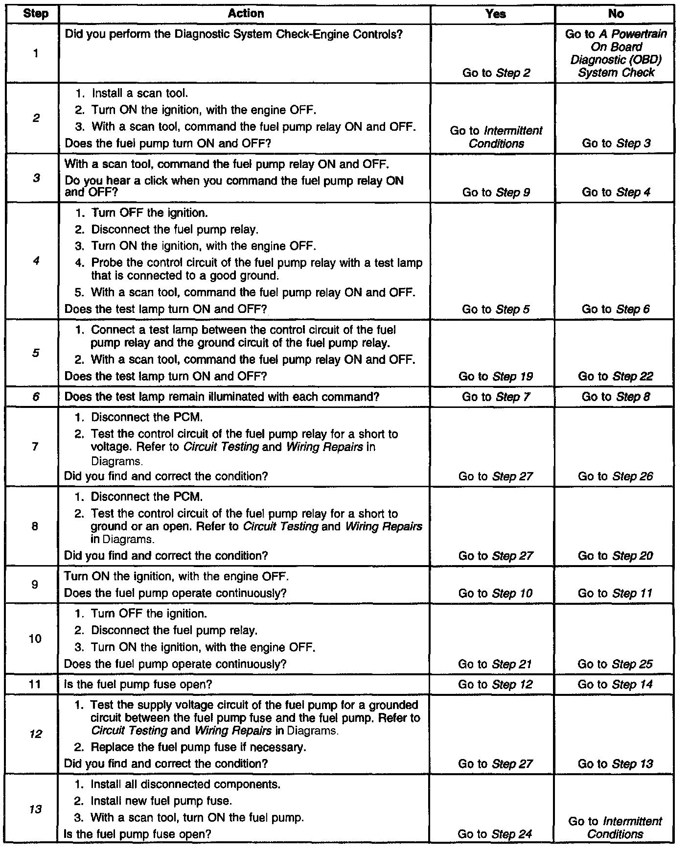
Diagnostic Chart (Part 1 Of 2):
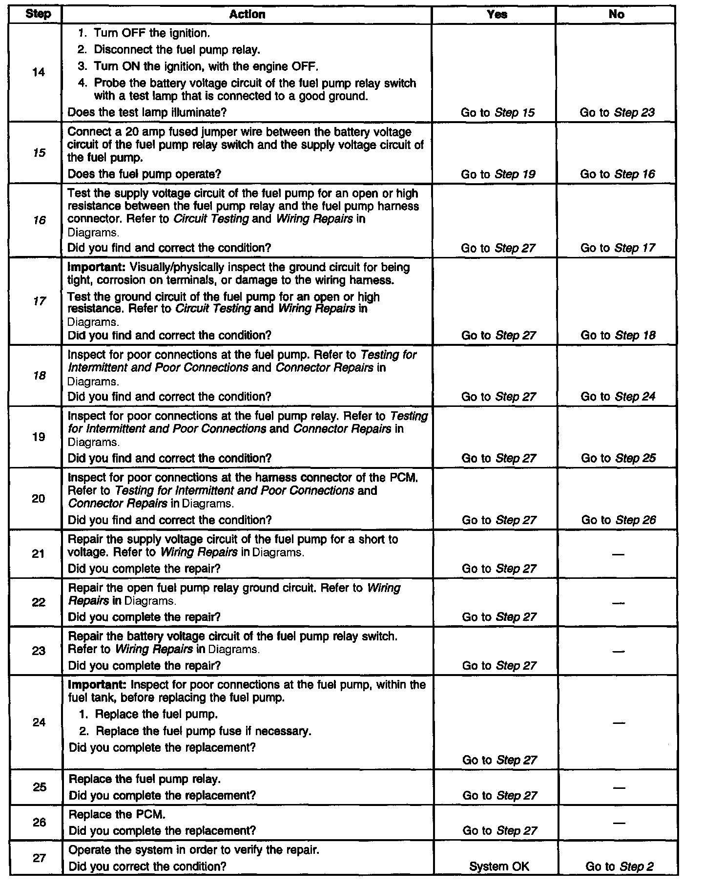
Diagnostic Chart (Part 2 Of 2):
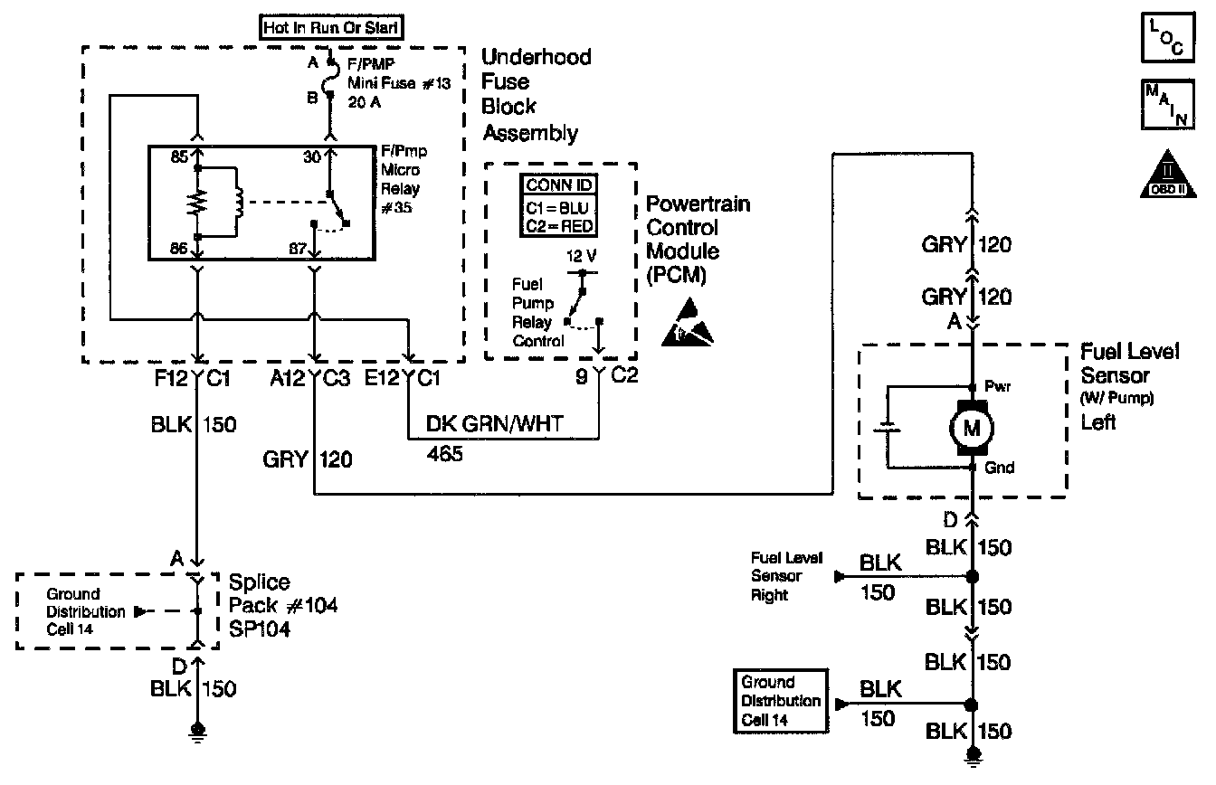
Schematic:
CIRCUIT DESCRIPTION
When you turn ON the ignition switch, the Powertrain Control Module (PCM) activates the in-tank fuel pump. The in-tank fuel pump remains ON as long as the engine is cranking or running and the PCM receives reference pulses from the ignition system. If there are no reference pulses, the PCM turns the in-tank fuel pump OFF after about 2-3 seconds.
The electric fuel pump attaches to the fuel sender assembly inside the left fuel tank. The in-tank fuel pump supplies fuel through an in-pipe fuel filter/fuel pressure regulator assembly to the fuel rail. The fuel pump also supplies fuel to the right fuel tank siphon jet pump in order to transfer fuel from the right fuel tank to left fuel tank. The fuel pump provides fuel at a pressure above the pressure needed by the fuel injectors. The fuel pressure regulator, part of the fuel filter, keeps the fuel available to the fuel injectors at a regulated pressure. Unused fuel returns to the left fuel tank by a separate fuel return pipe.
Improper fuel system pressure results in one or many of the following symptoms:
^ Cranks but will not run
^ Cuts out, may feel like an ignition system
^ Poor fuel economy
^ Loss of power
^ Hesitation
DIAGNOSTIC AIDS
IMPORTANT:
^ Remove any debris from the PCM connector surfaces before servicing the PCM. Inspect the PCM connector gaskets when diagnosing/replacing the module. Ensure that the gaskets are installed correctly. The gaskets prevent contaminate intrusion into the PCM.
^ For any test that requires probing the PCM or a component harness connector, use the Connector Test Adapter Kit J 35616-A. Using this kit prevents damage to the harness/component terminals. Refer to Using Connector Test Adapters in Diagrams.
The following conditions may have caused the fuel pump fuse to open:
^ The fuse was faulty.
^ There is an intermittent short in the fuel pump power feed circuit.
^ The fuel pump has an internal intermittent condition.
For an intermittent condition, refer to Symptoms. Symptom Related Diagnostic Procedures
TEST DESCRIPTION
The numbers below refer to the step numbers on the diagnostic table.
2. Command both the ON and OFF states. Repeat the commands as necessary.
3. This step determines if the condition is located on the coil side or the switch side of the circuit.
4. Verifies that the powertrain control module is providing voltage to the fuel pump relay.
5. Tests for an open in the ground circuit to the fuel pump relay.
6. This step determines if a voltage is constantly being applied to the fuel pump relay.
12. Tests for a grounded supply circuit between the fuel pump relay and the fuel pump harness connector.
13. This step determines if the condition with the circuit is intermittent. If the fuse does not open, inspect the supply voltage circuit between the fuse and the fuel pump for an intermittent condition.
15. This step determines if the fuel pump relay is causing the condition. Use the appropriate size fused jumper wire.
16. Tests for an open or excessive resistance in the supply circuit between the fuel pump relay and the fuel pump harness connector.
17. Inspect the fuel pump ground circuit thoroughly. A poor connection or corrosion will cause the fuel pump to be inoperative.
18. This step inspects for a poor connection or corrosion at the fuel pump harness connector which could cause the condition.