Service Procedure
Important:The service procedure contained in this program is different from the service procedure found in the appropriate service manual. As a result, the labor time allowance has been revised to correspond with this new service procedure.
Flywheel and Clutch Assembly Inspection for 2006 Chevrolet Corvette Vehicles Equipped with a 6.0L (LS2) or 7.0L (LS7) Engine and 6-Speed Manual Transmission (MM6/MZ6)
There are six bolts that attach the clutch pressure plate cover to the flywheel. Only three of the six bolt holes on the flywheel have adjacent locating pins. The flywheel has alternating deep and shallow flywheel rim steps. Some flywheels were produced with the locating pin adjacent to the wrong step location. If the locating pins are next to the wrong bolt holes on the flywheel, the clutch cover ends up indexed improperly (off one bolt hole), which may cause interference between the flywheel and the clutch pressure plate cover. Refer to the flywheel Inspection photographs below before performing the flywheel Inspection procedure.
Flywheel Inspection Photographs
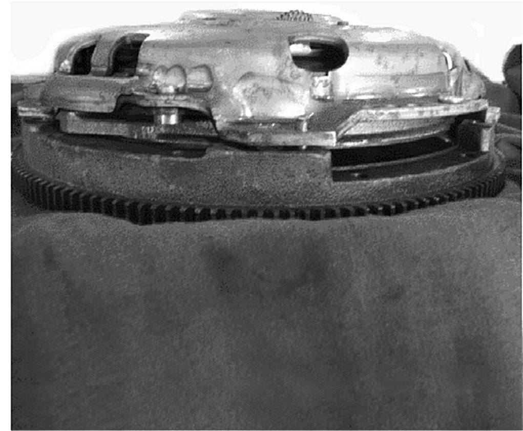
Bad Flywheel/Clutch Plate Assembly w/shallow rim step to left of bolt/locating pin machined pad.
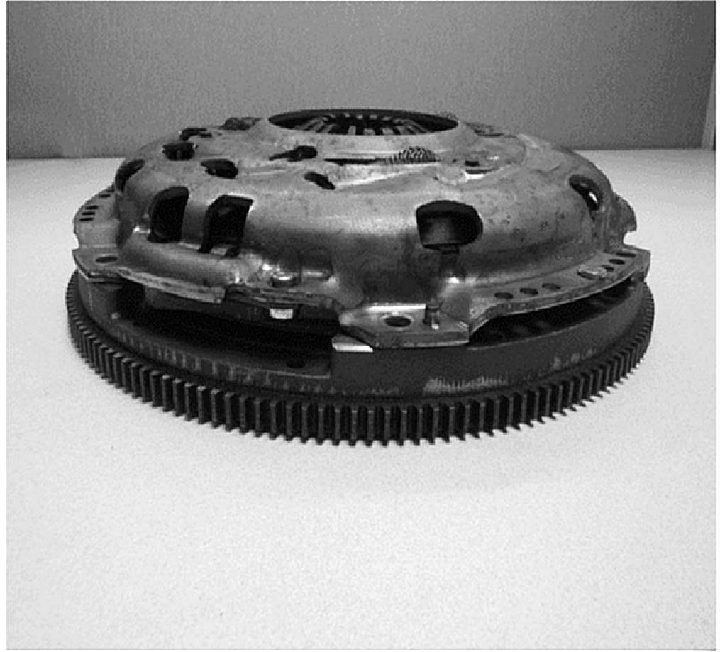
Good Flywheel/Clutch Plate Assembly w/deep rim step to left of bolt/locating pin machined pad.
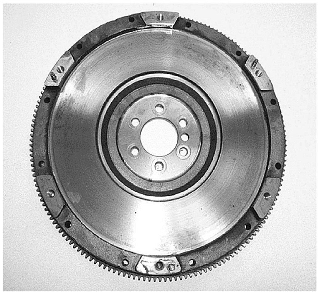
Bad Flywheel w/incorrect rim step locating pin placement
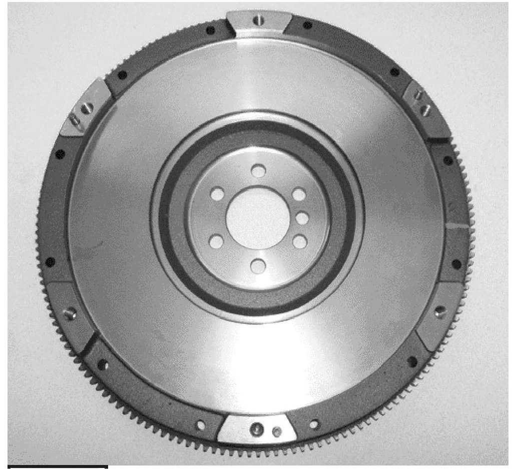
Good Flywheel w/correct rim step locating pin placement
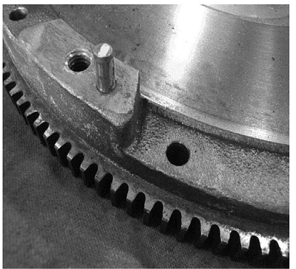
Bad Flywheel w/deep rim step to right of locating pin
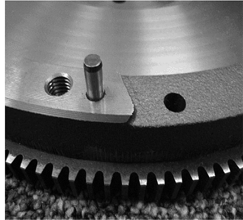
Good Flywheel w/shallow rim step to right of locating pin
Flywheel Inspection
1. Raise and support the vehicle.
Important:
Only three of the six clutch pressure plate cover bolts (1) have the locating pin (1) next to them.
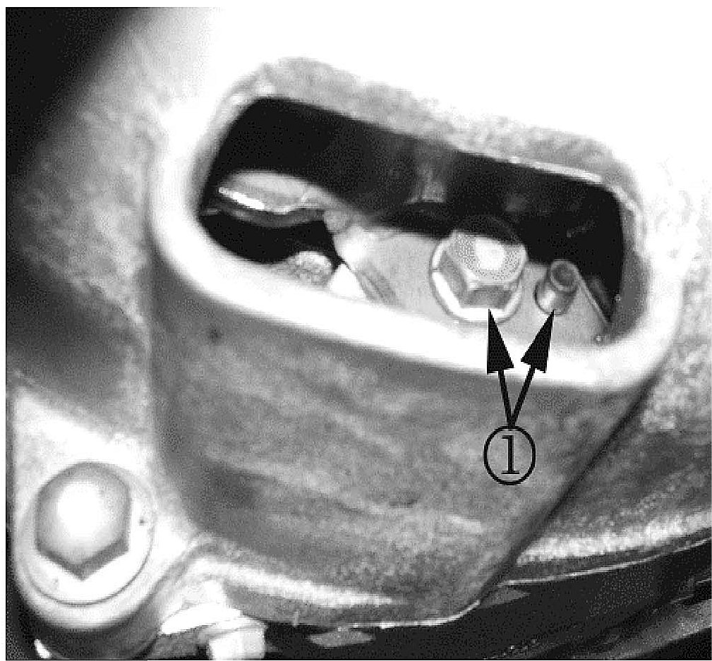
2. Position the flywheel so that one of the three clutch pressure plate cover bolts (1) with a locating pin (1) is visible in the left (driver's side) vent opening of the bell housing.
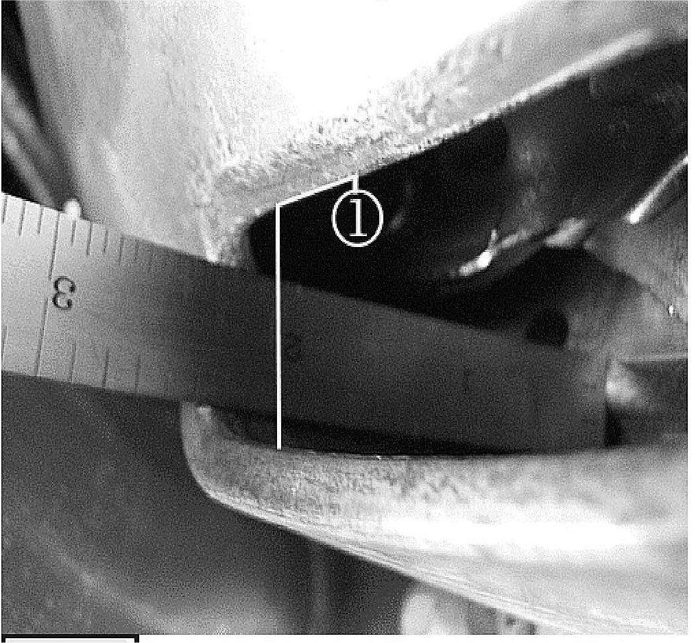
Important:
Ensure measurement is from the non-machined rim surface of the flywheel and NOT the machined pad for the clutch pressure plate cover.
3. Measure the distance between the non-machined rim surface at the left of the machined pad of the flywheel to the edge of the bell housing vent openings. Ensure that the flywheel position is the same as shown in Step 2.
^ If the flywheel measurement is about 60.5 mm (2-3/8 in), the flywheel is indexed properly. No further action is required.
^ If the flywheel measurement is about 50.8 mm (2 in), the flywheel is NOT indexed properly. Refer to clutch Assembly Inspection in this bulletin.
Clutch Assembly Inspection
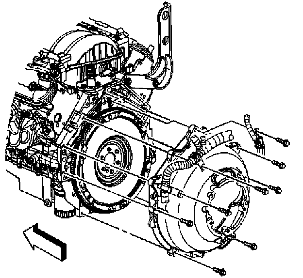
Important:
The bell housing must be removed from the engine before you can inspect the clearance between the rivet head on the clutch pressure plate cover and the raised step on the flywheel.
1. Refer to clutch Assembly Replacement procedure for the 6.0L (LS2) engine or 7.0L (LS7) engine in SI.
2. Perform the inspection after the bell housing has been removed from the engine. Do not remove clutch assembly before performing inspection.
3. Inspect the clearance between each rivet head on each pressure plate plug and the raised step on the flywheel. There are three locations on the clutch pressure plate to inspect.
3.1. Rotate the flywheel where it is attached to the engine to bring each pressure plate plug rivet head into view.
3.2. Use a feeler gauge with a stock thickness of 0.05 mm (0.002 inch) to determine if there is interference between each of the pressure plate plug rivet heads and the flywheel step.
3.3. Slide the feeler gauge horizontally along the shallow flywheel step.
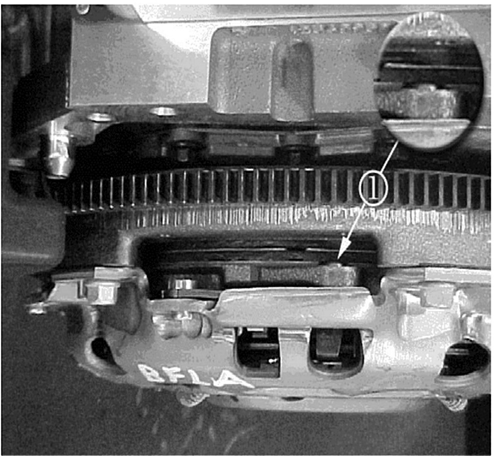
^ The clearance between each of the three pressure plate plug rivet heads (1) and flywheel step must be 6 mm (15/64 inch) or greater at all three locations. If the clearance between the pressure plate plug rivet head (1) and the flywheel step is 6 mm (15/64 inch) or greater at all three locations, the flywheel does not require replacement. Reassemble the vehicle components and proceed to step 5. Refer to clutch Assembly procedure for the 6.0L (LS2) engine or 7.0L (LS7) engine in SI.
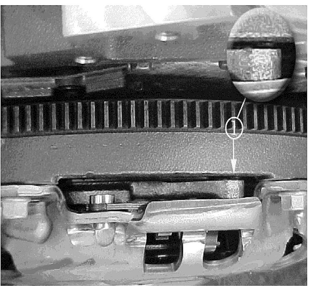
^ If the clearance between the pressure plate plug rivet head (1) and the flywheel step is greater than 0.05 mm (0.0002 inch), but is less than 6 mm (15/64 inch) at any of the three pressure plate plug rivet head (1) and flywheel step locations, replace the flywheel only Perform service procedure steps 2, 3 and 5. Refer to information in third bulletin point before replacing the flywheel.
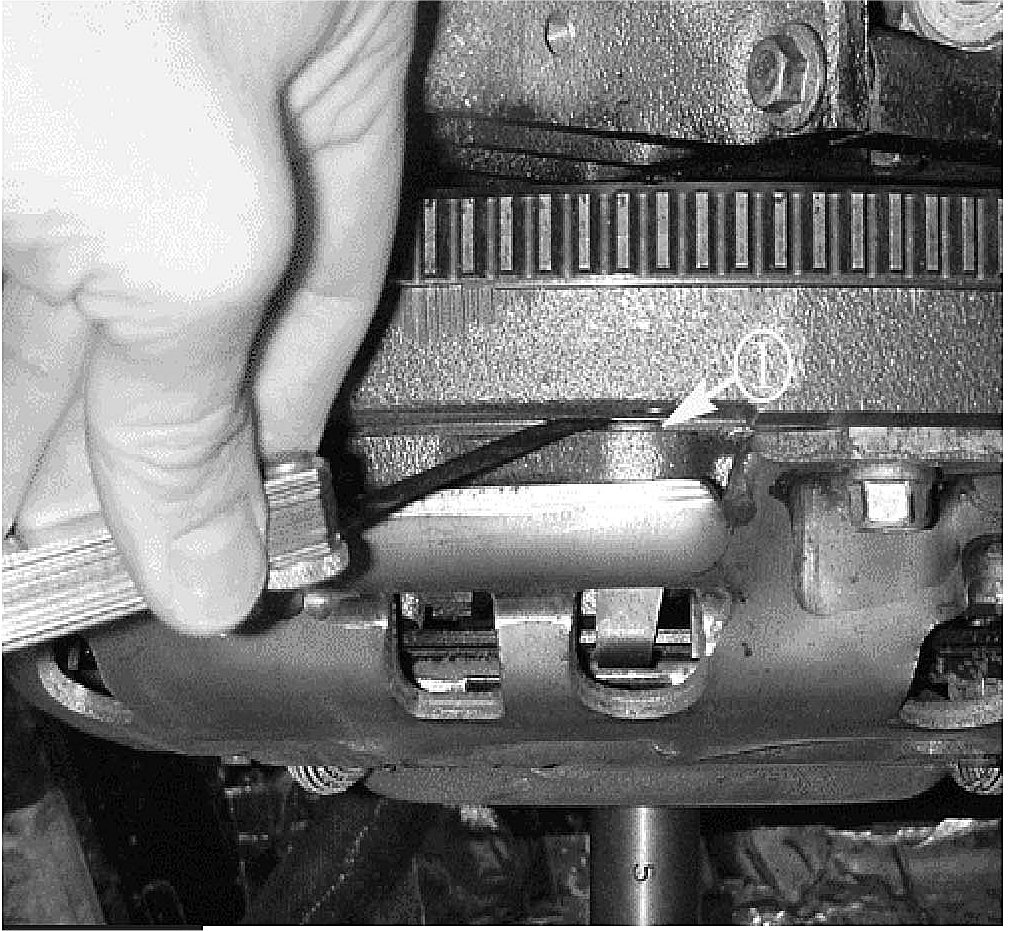
^ If there is less than 0.05 mm (0.0002 .inch) clearance between any of the pressure plate plug rivet heads (1) and flywheel step locations, the flywheel and clutch assembly must be replaced. Perform service procedure steps 2-5.
Important:
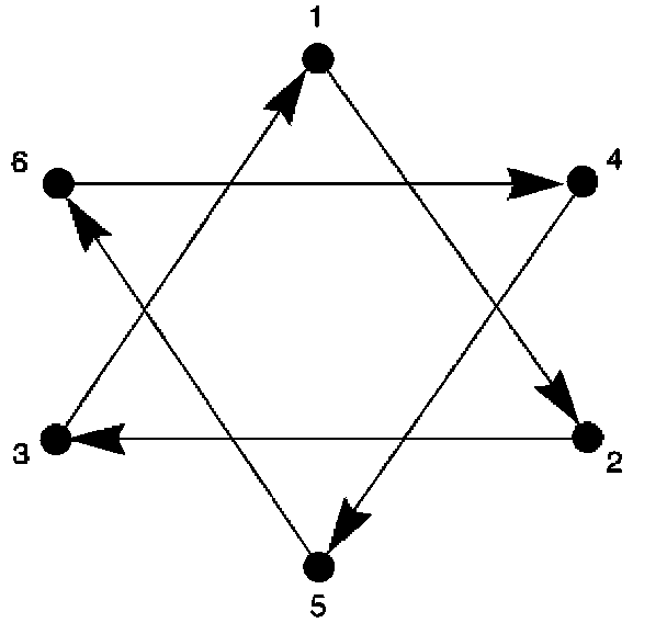
Remove the clutch pressure plate bolts in the sequence shown, starting with the number one and following in numerical order.
2. Remove the flywheel. Refer to Engine Flywheel Replacement and Engine flywheel Removal procedures for the 6.0L (LS2) engine or 7.0L (LS7) engine in SI.
Important:
During the powertrain build process, balance weights may be added to the flywheel. Install the same size balance weights onto the new flywheel in the same location as the old flywheel. Apply Threadlocker--Red, GM P/N 12345382 (Canadian P/N 10953489), or equivalent, to balance weights before pressing them into the flywheel.
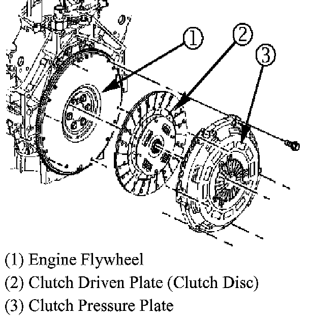
3. Install new flywheel (P/N 12571611). Refer to Engine Flywheel Installation and Engine Flywheel Replacement Procedures for the 6.0L (LS2) engine or 7.0L (LS7) engine in SI.
Important:
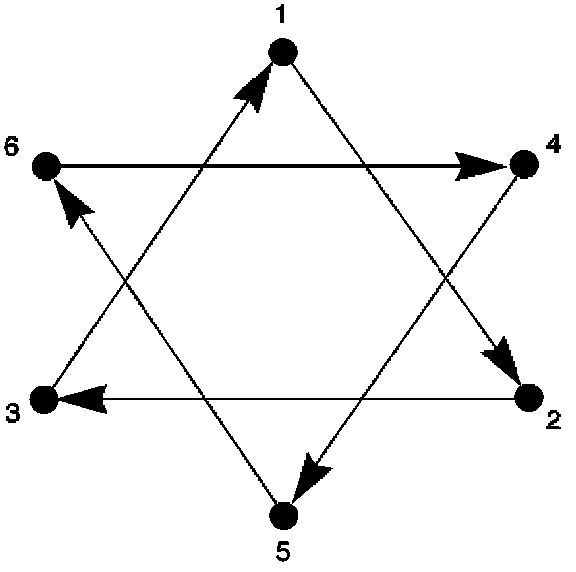
Remove the clutch pressure plate bolts in the sequence shown, starting with the number one and following in numerical order.
4. Install a new clutch kit, P/N 24233084 (LS2) P/N 24236500 (LS7) and assemble vehicle components. Refer to clutch Assembly Replacement procedure for the 6.0L (LS2) engine or 7.0L (LS7) engine in SI.
5. Perform vehicle road test.