Crankshaft: Service and Repair
Crankshaft Replacement
Tools Required
* DW110-170-02 Piston Ring Compressor (2.5L) or equivalent
* EN-47617 (DW110-190) Crankshaft Adjuster
* EN-47616 (DW110-180-02) Crankshaft Rear Oil Seal Installer
* EN-47615 (DW110-180-01) Crankshaft Front Oil Seal Installer
Removal Procedure
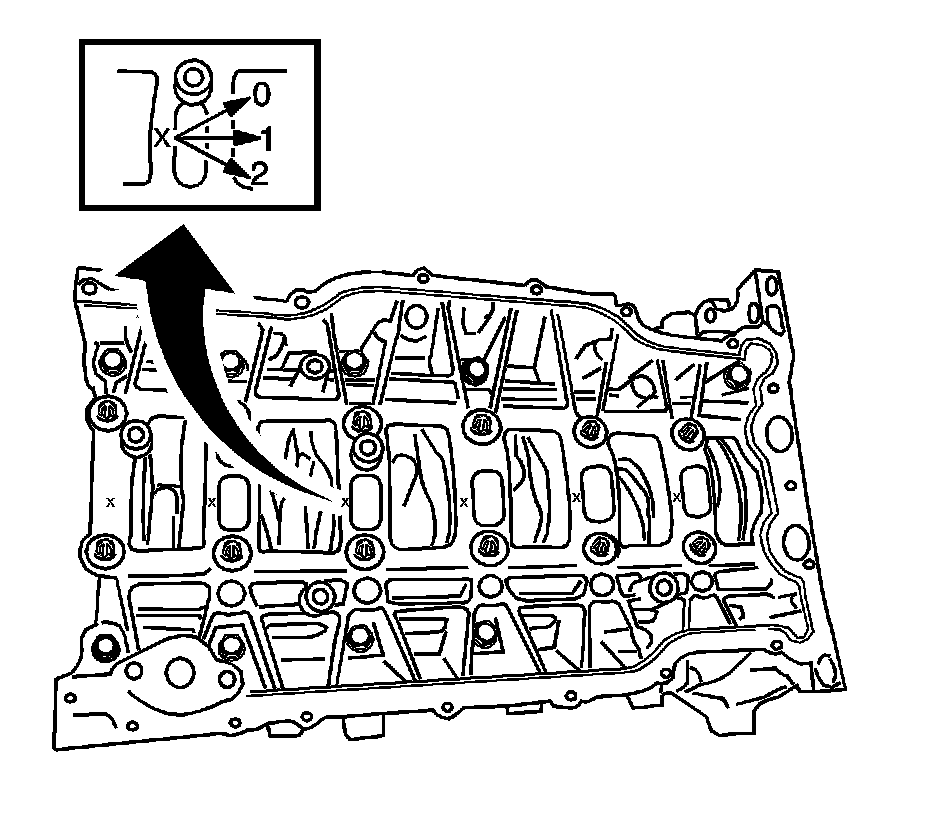
Important: The sizes of each upper crankshaft bearing are marked on the bed plate as shown in the illustration.
1. Remove the lower crankcase. Refer to Lower Crankcase Replacement Service and Repair.
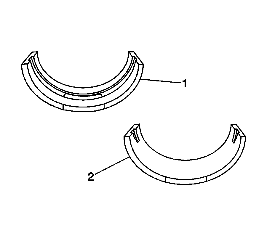
Important: The lower crankshaft bearings have different groove shape and the sizes of the crankshaft bearings are identified by the color marks on the side of the bearings, which are green (Size - 0), yellow (Size - 1), and pink (Size - 2).
2. Remove the lower crankcase bearings.
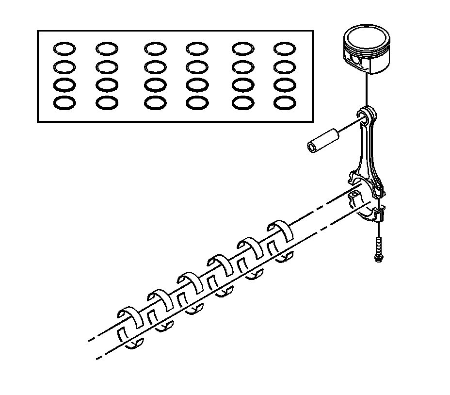
3. Move the piston to the bottom of the piston stroke.
4. Mark the connecting rod cap for position.
5. Remove the connecting rod caps and bearings.
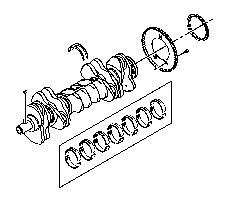
6. Remove the piston.
7. Remove the piston rings.
8. Remove the crankshaft.
9. Remove the upper connecting rod bearing.
10. Remove the rear crankshaft seal.
Installation Procedure
1. Installation should follow the removal procedure in the reverse order.
Important: The sizes of each upper crankshaft bearing are marked on the bed plate as shown in the illustration.
2. Install the upper crankshaft bearings.
Important: The lower crankshaft bearings have different groove shape and the sizes of the crankshaft bearings are identified by the color marks on the side of the bearing, which are green (Size - 0), yellow (Size - 1), and pink (Size - 2).
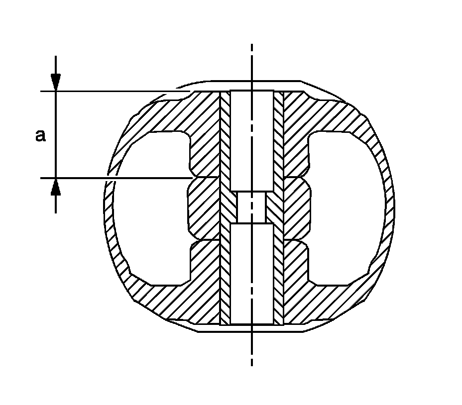
3. Install the crankshaft.
4. Install the piston pin.
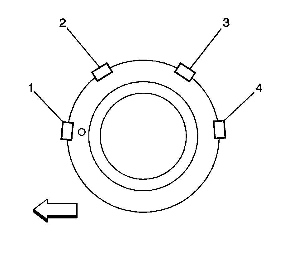
Notice: Use a piston ring expander to install the piston rings. The rings may be damaged if expanded more than necessary.
5. Install the piston rings.
6. Stagger the piston oil rings, the upper oil ring rail gap (2), the lower oil ring rail gap (3), the second compression ring (1), and the top compression ring (4) in relation to the front of the engine, as shown.
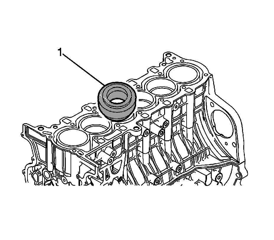
7. Install the piston using the DW110-170-02 . Observe the installation order of the piston as follows: 2 -5-1-3-4, piston number.
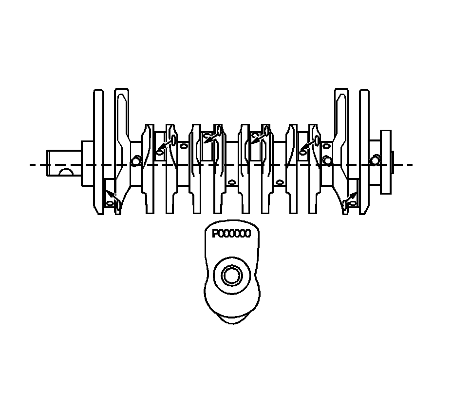
Important: The sizes of the connecting rod bearings are identified by the color marks on the side of the bearing, which are green (Size - 0) and yellow (Size - 1).
8. Seat the connecting rod bearings and temporarily install the connecting rod cap.

Important: Make sure the oil groove on the thrust bearing is installed facing outside.
9. Install the thrust bearing.
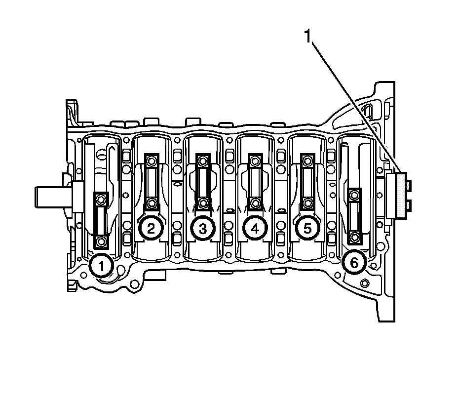
10. Tighten the connecting rod cap bolts using the EN-47617 (1). Observe the tightening order of the connecting rod cap bolts as follows: 2-5-1-6-3-4, piston number.
Tighten the connecting rod cap bolts to 20 Nm (15 lb ft). After finishing the initial tightening, turn the bolts by 45 degrees, than another 90 degrees.
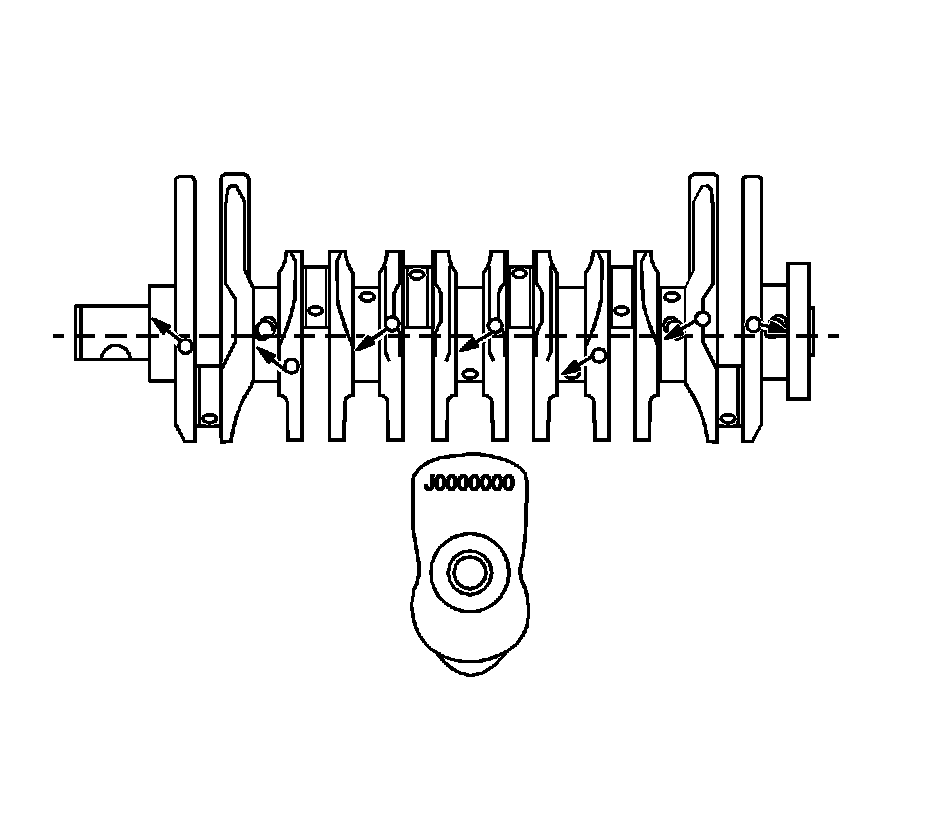
Important: The lower crankshaft bearings have different groove shape and the sizes of the crankshaft bearings are identified by the color marks on the side of the bearing, which are green (Size - 0), yellow (Size - 1), and pink (Size - 2).
11. Install the lower crankshaft bearing.
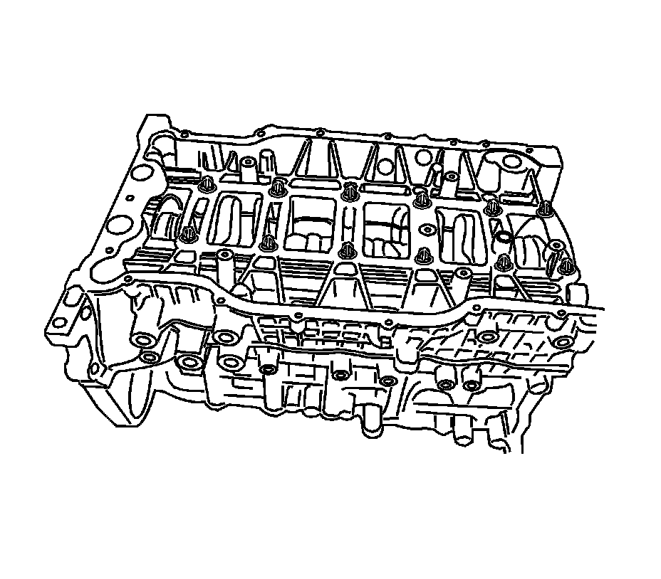
12. Install the lower crankcase. Refer to Lower Crankcase Replacement Service and Repair.
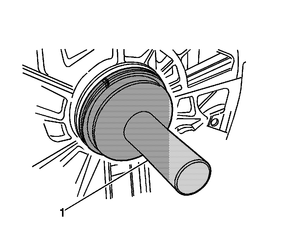
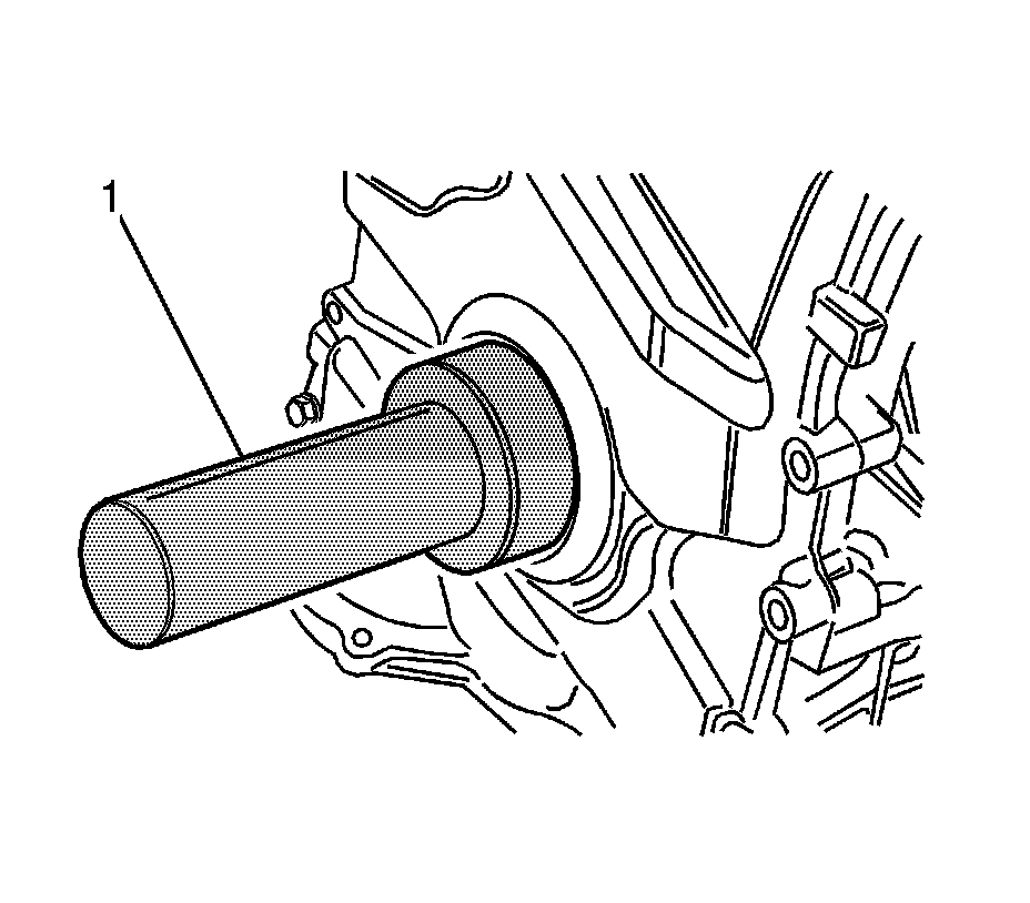
13. Seat and install the crankshaft rear oil seal using the EN-47616 (1).
14. Install the cylinder head. Refer to Cylinder Head Replacement Service and Repair.
15. Install the timing chain cover. Refer to Timing Chain and Sprockets Replacement Service and Repair.
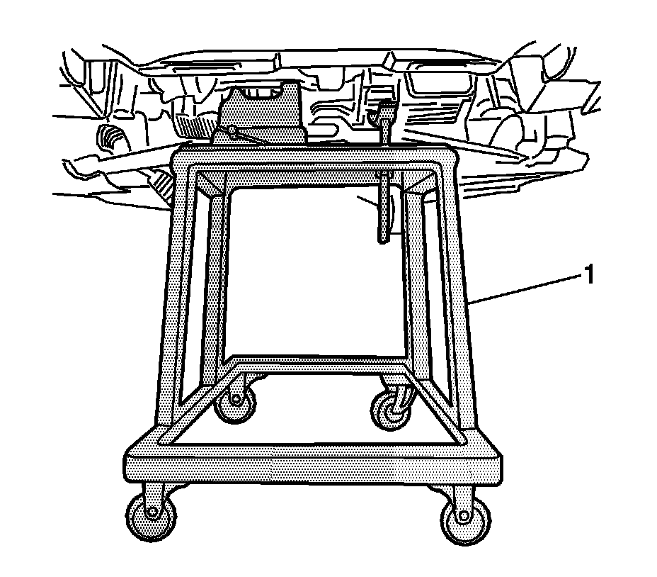
16. Install the crankshaft front oil seal using the EN-47615 (1).
17. Install the cylinder head cover. Refer to Cylinder Head Cover Replacement Service and Repair.
18. Install the intake manifold. Refer to Intake Manifold Replacement Service and Repair.
19. Install the engine assembly. Refer to Engine Replacement Removal and Replacement.