Door Ajar Indicator Malfunction
Door Ajar Indicator Malfunction
Diagnostic Instructions
* Perform the Diagnostic System Check - Vehicle Diagnostic System Check - Vehicle prior to using this diagnostic procedure.
* Review Strategy Based Diagnosis Strategy Based Diagnosis for an overview of the diagnostic approach.
* Diagnostic Procedure Instructions Diagnostic Procedure Instructions provides an overview of each diagnostic category.
Diagnostic Fault Information
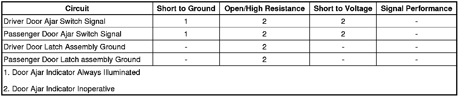
Circuit/System Description
The driver window motor supplies a reference voltage to the driver door ajar switch and the passenger window motor supplies a reference voltage to the passenger door ajar switch. The door ajar switches are normally open when the doors are fully closed. When a door is opened, the door ajar switch contacts close providing a path to ground. The respective window motor detects the drop in the reference voltage and will send a serial data message to the body control module (BCM) indicating the door is ajar, the BCM in turn sends a serial data message to the driver information center which displays the appropriate door ajar message.
Reference Information
Schematic Reference
Door Lock/Indicator Schematics Door Lock/Indicator Schematics
Connector End View Reference
Component Connector End Views Fuel Pump and Level Sensor Assembly - Primary
Description and Operation
Power Door Locks Description and Operation Description and Operation
Electrical Information Reference
* Circuit Testing Circuit Testing
* Connector Repairs Connector Repairs
* Testing for Intermittent Conditions and Poor Connections Testing for Intermittent Conditions and Poor Connections
* Wiring Repairs Wiring Repairs
Scan Tool Reference
Control Module References Control Module References for scan tool information
Circuit/System Verification
1. Ignition ON.
2. Verify the scan tool Driver Door Ajar Switch parameter changes between Inactive and Active when opening and closing the driver door.
• If the parameter does not change
Refer to Circuit/System Testing - Driver Door Ajar Switch
• If the parameter changes
3. Verify the scan tool Passenger Door Ajar Switch parameter changes between Inactive and Active when opening and closing the passenger door.
• If the parameter does not change
Refer to Circuit/System Testing - Passenger Door Ajar Switch
• If the parameter changes
4. All OK.
Circuit/System Testing
Driver Door Ajar Switch
1. Ignition OFF and all vehicle systems OFF, disconnect the harness connector at the A23D door latch assembly-driver. It may take up to 2 minutes for all vehicle systems to power down.
2. Test for less than 10 ohms between the ground circuit terminal 8 and ground.
• If 10 ohms or greater
1. Ignition OFF.
2. Test for less than 2 ohms in the ground circuit end to end.
• If 2 ohms or greater, repair the open/high resistance in the circuit.
• If less than 2 ohms, repair the open/high resistance in the ground connection.
• If less than 10 ohms
3. Ignition ON.
4. Verify the scan tool Driver Door Ajar Switch parameter is Inactive.
• If not Inactive
1. Ignition OFF, disconnect the harness connector at the M74D window motor-driver
2. Test for infinite resistance between the signal circuit terminal 6 and ground.
• If less than infinite resistance, repair the short to ground on the circuit.
• If infinite resistance, replace the M74D window motor-driver.
• If Inactive
5. Install a 3 A fused jumper wire between the signal circuit terminal 6 and the ground circuit terminal 8.
6. Verify the scan tool Driver Door Ajar Switch parameter is Active.
• If not Active
1. Ignition OFF, disconnect the harness connector at the M74D window motor-driver, ignition ON.
2. Test for less than 1 V between the signal circuit and ground.
• If 1 V or greater, repair the short to voltage on the circuit.
• If less than 1 V
3. Test for less than 2 ohms in the signal circuit end to end.
• If 2 ohms or greater, repair the open/high resistance in the circuit.
• If less than 2 ohms, replace the M74D window motor-driver.
• If Active
7. Test or replace the A23D door latch assembly-driver.
Passenger Door Ajar Switch
1. Ignition OFF and all vehicle systems OFF, disconnect the harness connector at the A23P door latch assembly-passenger. It may take up to 2 minutes for all vehicle systems to power down.
2. Test for less than 10 ohms between the ground circuit terminal 3 and ground.
• If 10 ohms or greater
1. Ignition OFF.
2. Test for less than 2 ohms in the ground circuit end to end.
• If 2 ohms or greater, repair the open/high resistance in the circuit.
• If less than 2 ohms, repair the open/high resistance in the ground connection.
• If less than 10 ohms
3. Ignition ON.
4. Verify the scan tool Passenger Door Ajar Switch parameter is Inactive.
• If not Inactive
1. Ignition OFF, disconnect the harness connector at the M74P window motor-passenger.
2. Test for infinite resistance between the signal circuit terminal 6 and ground.
• If less than infinite resistance, repair the short to ground on the circuit.
• If infinite resistance, replace the M74P window motor-passenger.
• If Inactive
5. Install a 3 A fused jumper wire between the signal circuit terminal 1 and the ground circuit terminal 3.
6. Verify the scan tool Passenger Door Ajar Switch parameter is Active.
• If not Active
1. Ignition OFF, disconnect the harness connector at the M74P window motor-passenger, ignition ON.
2. Test for less than 1 V between the signal circuit and ground.
• If 1 V or greater, repair the short to voltage on the circuit.
• If less than 1 V
3. Test for less than 2 ohms in the signal circuit end to end.
• If 2 ohms or greater, repair the open/high resistance in the circuit.
• If less than 2 ohms, replace the M74P window motor-passenger.
• If Active
7. Test or replace the A23P door latch assembly-passenger.
Component Testing
1. Ignition OFF, disconnect the harness connector at the appropriate A23 door latch assembly.
2. Test for infinite resistance between the signal terminal 4 and the ground terminal 2 with the switch in the open position.
* Signal terminal 6 and ground terminal 8 - A23D door latch assembly-driver
* Signal terminal 1 and ground terminal 3 - A23P door latch assembly-passenger
• If less than infinite resistance
Replace the A23 door latch assembly.
• If infinite resistance
3. Test for less than 3 ohms between the signal and the ground terminal listed below with the switch in the closed position.
* Signal terminal 6 and ground terminal 8 - A23D door latch assembly-driver
* Signal terminal 1 and ground terminal 3 - A23P door latch assembly-passenger
• If 3 ohms or greater
Replace the A23 door latch assembly.
• If less than 3 ohms
4. All OK
Repair Instructions
Perform the Diagnostic Repair Verification Verification Tests after completing the diagnostic procedure.
* Front Side Door Latch Replacement Service and Repair
* Front Side Door Window Regulator Motor Replacement Service and Repair