With Electronic Spark Control (ESC)
Ignition System Checkout1. Remove the coil wire from distributor cap and hold end of wire about 1/4 in. from a good engine ground. Turn ignition "On," then intermittently jump coil negative terminal to a good ground while observing coil wire.
2. The spark at the coil wire must be constant and bright blue. If spark is satisfactory, intermittently jump coil negative terminal while slowly moving coil wire end away from ground. If arcing occurs at the coil tower, replace coil. If spark is weak or not constant or there is no spark, proceed to the "Failure To Start Test."
3. If spark is satisfactory and no arcing occurs at coil tower, the ignition system is producing the necessary high secondary voltage. However, ensure this voltage is transmitted to the spark plugs by checking the distributor rotor, cap, spark plug wires, and spark plugs. If satisfactory, the ignition system is not faulty. It will be necessary to check the fuel system and engine mechanical components.
Failure To Start Test
1. Turn ignition "Off". Remove 10 way connector from base of Spark Control Computer. Turn ignition "On", then holding end of coil wire about 14 away from a ground, momentarily short coil negative wire to ground. If a spark is obtained, replace Spark Control Computer. If no spark is obtained, proceed to step 2.
2. Using a voltmeter, check for battery voltage at coil positive terminal with the ignition "On". If voltage is within 1 volt of battery voltage, proceed to step 4. If not, proceed to step 3.
3. Check continuity of wiring between battery and coil positive, repair as necessary and repeat step 2.
4. Using a voltmeter, check for battery voltage at coil negative. If within 1 volt of battery voltage, proceed to step 5. If not, replace coil.
5. If voltage is correct, but no spark is obtained when grounding coil negative, replace coil.
Dual Connector:
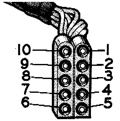
6. If spark is obtained, but engine will not start, place ignition switch in "On" position. Using a suitable voltmeter, measure voltage of disconnected 10 way connector cavity 1, to ground. Voltage should be within 1 volt of battery voltage. If voltage is within 1 volt of battery voltage, proceed to step 8. If not, proceed to step 7.
7. Check wire for opens and repair as necessary (no power between coil negative and 10 way connector). Repeat step 6.
Power And Vacuum Transducer Tests:
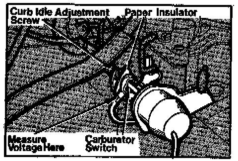
8. Place a piece of paper between curb idle adjusting screw and carburetor switch, or ensure curb idle adjusting screw is not contacting carburetor switch.
9. Connect negative lead of voltmeter to a good engine ground.
10. Rotate ignition switch to "On" position and measure voltage at carburetor switch terminal. If voltage is approximately 5 volts, proceed to step 12. If voltage is not at least 5 volts, place ignition switch in "Off" position and disconnect wire connector from bottom of Spark Control Computer, Fig. 1. Rotate ignition switch back to the "On" position and measure voltage at wire connector terminal 2, Fig. 1. Voltage should be within one volt of battery voltage noted previously. If voltage is correct proceed to step 11. If voltage is incorrect check wiring between wire terminal 2 and ignition switch for open or short circuits or improper connections.
11. With ignition switch in the "On" position, disconnect wire connector from Spark Control Computer. Using an ohmmeter check for continuity between connector terminal 7, Fig. 1, and carburetor switch terminal. Continuity should exist between these two points. If not, check wiring for open or short circuit or improper connections. If continuity is noted, check for continuity between connector terminal 10 and engine ground. If continuity exists, replace Spark Control Computer. If not, check wiring for open circuit or improper connections and proceed to step 12 only if engine still fails to start.
12. Place ignition switch in the "Off" position, then using an ohmmeter, measure resistance between terminals No. 5 and 9 for run pickup coil and terminals 3 and 9 for start pickup coil Fig. 1. Resistance should be between 150 and 900 ohms. If not, disconnect pickup coil leads from distributor and measure resistance at lead going into distributor. If resistance is now between 150 and 900 ohms, this would indicate an open or short circuit or improper connection between distributor connector and terminals 5 and 9 or terminals 3 and 9 of dual connector. If resistance is not within specifications, pickup coil is defective.
13. Connect one ohmmeter lead to engine ground and with the other lead check for continuity at each terminal going to the distributor. There should be no continuity. Reconnect distributor lead and proceed to step 14. If there is continuity, replace pickup coil.
14. Remove distributor cap and check air gap of pickup coil and adjust gap as necessary.
15. Install distributor cap and reconnect all wiring, then start engine. If engine fails to start, replace spark control computer.
16. After installing new computer and engine still fails to start, reinstall original computer and repeat test procedure since one of the test procedures may have been performed incorrectly.