P0121
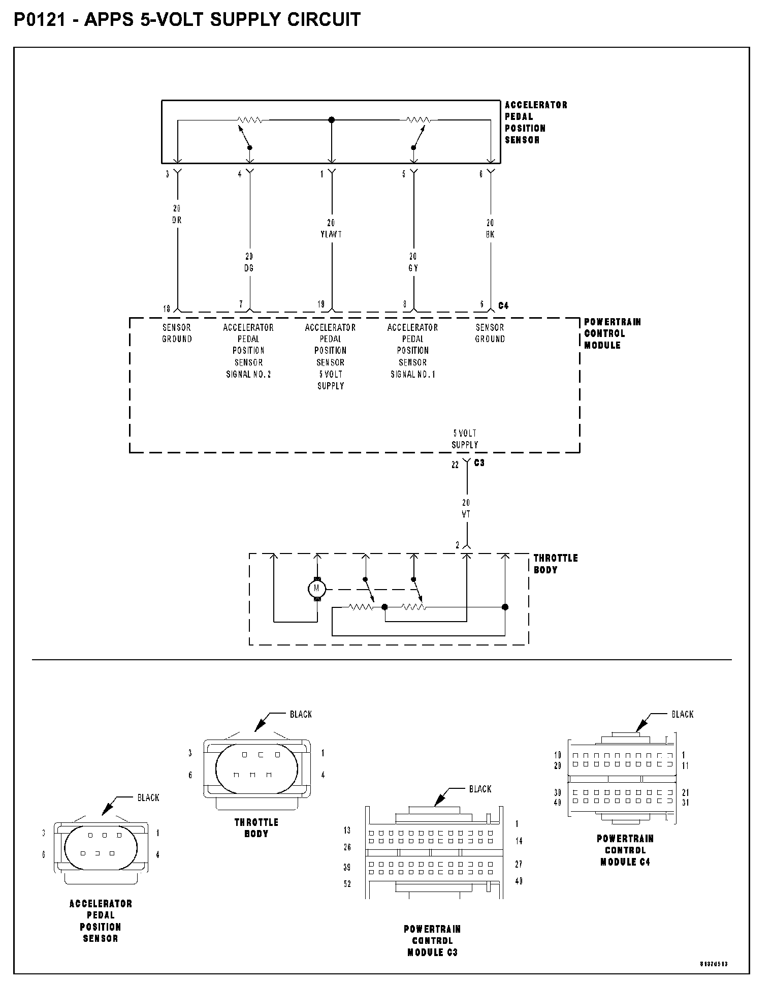
P0121 - APPS 5-VOLT SUPPLY CIRCUITP0121 - Apps 5-volt Supply Circuit:
WHEN MONITORED
Ignition on.
SET CONDITION
When the PCM recognizes the APP Sensor 5-Volt Supply circuit voltage is below 1.0 volt or higher than 5.2 volts.
POSSIBLE CAUSES
- APP sensor 5-volt supply circuit short to voltage
- APP sensor 5-volt supply circuit short to ground
- APP sensor 5-volt supply circuit short to sensor ground circuit(s)
- APP sensor 5-volt supply circuit open
- TP sensor 5-volt supply circuit short to voltage
- TP sensor 5-volt supply circuit short to ground
- TP sensor 5-volt supply circuit short to sensor ground circuit(s)
- Accelerator pedal position sensor
- Powertrain control module
DIAGNOSTIC TEST
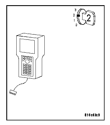
1. PRE-DIAGNOSTIC CHECK OUT
NOTE:
- Always perform diagnostics with a fully charged battery.
- Check connectors - Clean/repair as necessary. Poor pin to terminal connections can set DTCs.
- Check for applicable TSBs related to the problem.
Turn the ignition on.
With the DRB III(R), read PCM DTCs.
Using the wiring diagram/schematic as a guide, inspect the wiring and connectors.
Repair as necessary.
Perform this procedure prior to symptom diagnosis.
Continue
Go To 2
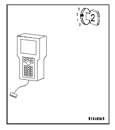
2. CHECK FOR CURRENT DTC
NOTE:
- If the PCM detects and stores a DTC, the PCM also stores the engine/ vehicle operating conditions under which the DTC was set. Some of these conditions are displayed on the DRB III(R) at the same time the DTC is displayed.
- Before erasing stored DTCs, record these conditions. Attempting to duplicate these conditions may assist when checking for a DTC.
Turn the ignition on.
With the DRB III(R), clear PCM DTCs.
NOTE: It maybe necessary to road test the vehicle for this DTC to set.
With the DRB III(R), read PCM DTCs.
Q: Did this DTC set again?
YES: Go To 3
NO: Go To 11
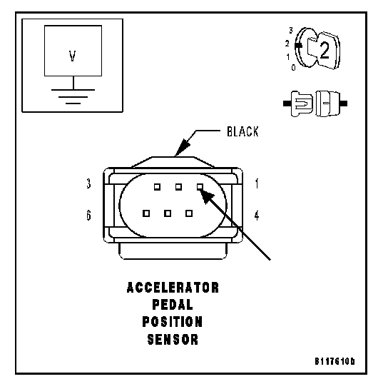
3. CHECK THE APP SENSOR 5-VOLT SUPPLY CIRCUIT VOLTAGE
Turn the ignition off.
Disconnect the APP Sensor harness connector.
NOTE: Check connectors - Clean/repair as necessary.
Turn the ignition on.
Measure the voltage of the APP Sensor 5-Volt Supply circuit at the APP Sensor harness connector.
Q: Is the voltage between 4.7 and 5.2 volts?
YES: Go To 4
NO: If the voltage is above 5.2 volts, Go To 5
If the voltage is below 4.7 volts, Go To 7
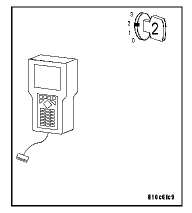
4. CHECK THE APPS
With the ignition on.
With the DRB III(R), clear PCM DTCs.
NOTE: It maybe necessary to road test the vehicle for this DTC to set.
With the DRB III(R), read the PCM DTCs.
Q: Did this DTC set again?
YES: Go To 9
NO: Replace the Accelerator Pedal Position Sensor. Perform POWERTRAIN VERIFICATION TEST - VER 2. Powertrain Verification Test - Ver 2
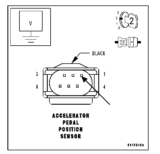
5. CHECK THE APP SENSOR 5-VOLT SUPPLY CIRCUIT FOR A SHORT TO VOLTAGE
Turn the ignition off.
Disconnect the PCM C4 harness connector.
NOTE: Check connectors - Clean/repair as necessary.
Turn the ignition on.
Measure the voltage of the APP Sensor 5-Volt Supply circuit at the APP Sensor harness connector.
Q: Is the voltage below 1.0 volt?
YES: Go To 6
NO: Repair the APP Sensor 5-Volt Supply circuit for a short to voltage.
Perform POWERTRAIN VERIFICATION TEST - VER 2. Powertrain Verification Test - Ver 2
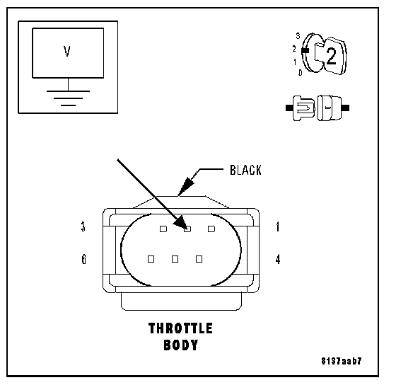
6. CHECK THE TP SENSOR 5-VOLT SUPPLY CIRCUIT FOR A SHORT TO VOLTAGE
Turn the ignition off.
Disconnect the PCM C3 harness connector.
Disconnect the Throttle Body harness connector.
NOTE: Check connectors - Clean/repair as necessary.
Turn the ignition on.
Measure the voltage of the 5-Volt Supply circuit at the Throttle Body harness connector.
Q: Is the voltage below 1.0 volt?
YES: Replace and program the Powertrain Control Module.
Perform POWERTRAIN VERIFICATION TEST - VER 2. Powertrain Verification Test - Ver 2
NO: Repair the 5-Volt Supply circuit for a short to voltage.
Perform POWERTRAIN VERIFICATION TEST - VER 2. Powertrain Verification Test - Ver 2
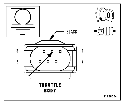
7. MEASURE THE RESISTANCE BETWEEN GROUND AND THE TP SENSOR 5-VOLT SUPPLY CIRCUIT
Turn the ignition off.
Disconnect the PCM C3 harness connector.
Disconnect the Throttle Body harness connector.
NOTE: Check connectors - Clean/repair as necessary. Measure the resistance between ground and the 5-Volt Supply circuit at the Throttle Body harness connector.
Q: Is the resistance above 100 kohms?
YES: Go To 8
NO: Repair the 5-Volt Supply circuit for a short to ground.
Perform POWERTRAIN VERIFICATION TEST - VER 2. Powertrain Verification Test - Ver 2
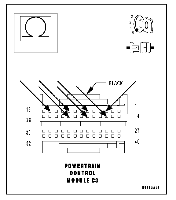
8. MEASURE RESISTANCE BETWEEN THE TP SENSOR 5-VOLT SUPPLY CIRCUIT AND SENSOR GROUND CIRCUITS
With the ignition off.
Measure the resistance between the 5-Volt Supply circuit and all Sensor Ground circuits in the PCM C3 harness connector.
Q: Is the resistance above 100 kohms for all measurements?
YES: Go To 9
NO: Repair the 5-Volt Supply circuit for a short to the Sensor Ground circuit that measured below 100 kohms.
Perform POWERTRAIN VERIFICATION TEST - VER 2. Powertrain Verification Test - Ver 2
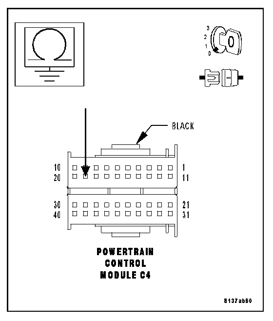
9. MEASURE THE RESISTANCE BETWEEN GROUND AND THE APP SENSOR 5-VOLT SUPPLY CIRCUIT
With the ignition off.
Disconnect the PCM C4 harness connector.
NOTE: Check connectors - Clean/repair as necessary. Measure the resistance between ground and the APP Sensor 5-Volt Supply circuit at the PCM C4 harness connector.
Q: Is the resistance above 100 kohms?
YES: Go To 10
NO: Repair the APP Sensor 5-Volt Supply circuit for a short to ground.
Perform POWERTRAIN VERIFICATION TEST - VER 2. Powertrain Verification Test - Ver 2
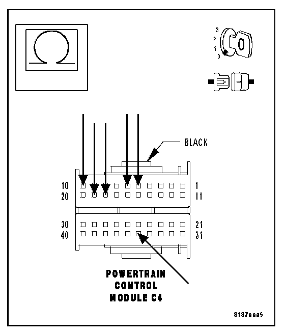
10. MEASURE RESISTANCE BETWEEN THE APP SENSOR 5-VOLT SUPPLY CIRCUIT AND SENSOR GROUND CIRCUITS
With the ignition off.
Measure the resistance between the APP Sensor 5-Volt Supply circuit and all Sensor Ground circuits in the PCM C4 harness connector.
Q: Is the resistance above 100 kohms for all measurements?
YES: Replace and program the Powertrain Control Module.
Perform POWERTRAIN VERIFICATION TEST - VER 2. Powertrain Verification Test - Ver 2
NO: Repair the APP Sensor 5-Volt Supply circuit for a short to the Sensor Ground circuit that measured below 100 k ohms. Perform POWERTRAIN VERIFICATION TEST - VER 2. Powertrain Verification Test - Ver 2
11. INTERMITTENT WIRING AND CONNECTORS
The condition that caused this DTC to set is currently not present. Inspect the related wiring harness for a possible intermittent condition.
NOTE:
- Check connectors - Clean/repair as necessary. Poor pin to terminal connections can set DTCs.
- Check for any Technical Service Bulletins that may apply. Using the wiring diagram/schematic as a guide, inspect the wiring and connectors
Specific to this DTC. Wiggle the
Wires while checking for shorts and open circuits.
Q: Were there any problems found?
YES: Repair as necessary.
Perform POWERTRAIN VERIFICATION TEST - VER 2. Powertrain Verification Test - Ver 2
NO: The condition that caused this DTC to set is currently not present. Inspect the related wiring harness for a possible intermittent condition.