Heating and Air Conditioning: Description and Operation
NOTES:- To maintain the performance level of the heating-air conditioning system, the engine cooling system must be properly maintained.
- The use of a bug screen is not recommended. Any obstructions in front of the radiator or condenser will reduce the performance of the air conditioning and engine cooling systems.
INTRODUCTION
Both the heater and the heater/air conditioning systems share many of the same components. This group will deal with both systems together when component function is common, and separately when they are not.
For proper operation of the instrument panel controls, refer to the Owner's Manual provided with the vehicle.
All vehicles are equipped with a common Heater-A/C unit housing assembly. When the vehicle has only a heater system, the evaporator is omitted.
Fig 1 Fixed Displacement Compressor -- Model 10PA15C:
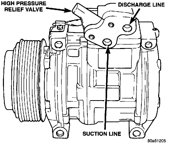
A/C SYSTEM IDENTIFICATION
The term Fixed Displacement Compressor will be used to describe the type of A/C system used throughout.
Fig 2 A/C Service Port Valve Location:
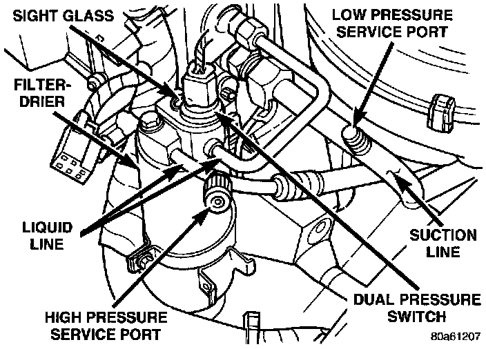
A/C SERVICE PORT VALVE CORES
The A/C service port valve cores are located within the A/C lines. The High Side (Discharge) valve service port is located near the filter - drier on the right side of the vehicle, behind the wheel well. The Low Side (Suction) valve service port is located near the filter - drier beside the air inlet.
AIR DISTRIBUTION DUCT
The instrument panel must be removed to service the Heater-A/C air distribution duct.
BLOWER MOTOR RESISTOR
The blower motor resistor is located in the engine compartment on the bottom side of the blower motor housing. The resistor can be removed without having to remove the blower motor housing from the vehicle.
COMPRESSOR HIGH PRESSURE RELIEF VALVE
The high pressure relief valve vents only a small amount of refrigerant necessary to reduce system pressure and then reseats itself. The majority of the refrigerant is conserved in the system. The valve is calibrated to vent at a pressure of 3,100 to 4,140 Kpa (450 to 600 psi). If a valve has vented a small amount of refrigerant, it does not necessarily mean the valve is defective.
CONDENSATE DRAIN TUBE
Condensation from the evaporator housing is drained by a rubber tube through the cowl panel and on to the ground. This tube must be kept open to prevent water from collecting in the bottom of the housing.
The tapered end of the drain tube is designed to keep contaminants from entering the Heater A/C unit housing. If the tube is pinched or blocked, condensate cannot drain, causing water to back up and spill into the passenger compartment. It is normal to see condensate drainage below the vehicle. If the tube is damaged, it should be replaced.
DUAL PRESSURE CUT OFF SWITCH
The Dual Pressure Cut-Off (DPCO) Switch monitors the refrigerant gas pressure in the A/C system. The DPCO is located on the filter-drier. Whenever the pressure drops below 196 to 248 kPa (28.4 to 36 psi) or exceeds 2,544 to 3,137 kPa (369 to 455 psi) (which could damage the compressor), the DPCO will open. The A/C switch sense circuit will open to the HVAC control causing the PCM to turn off the compressor clutch relay. The DPCO is a sealed factory calibrated unit. It must be replaced if defective.
ENGINE COOLING SYSTEM REQUIREMENTS
To maintain ample temperature levels from the heating-A/C system, the cooling system must be in proper working order. Refer to Cooling System.
The use of a bug screen is not recommended. Any obstructions forward of the condenser can reduce the effectiveness of the air conditioning system.
EVAPORATOR PROBE
The evaporator probe is a temperature sensing element located at the coldest point on the face of the evaporator. Output from the probe is sampled by the Powertrain Control Module. It is used to switch the clutch OFF before evaporator freeze up occurs. The clutch is switched OFF when the probe temperature reaches 1.1°C (34°F). It is allowed to switch ON when the probe temperature reaches 3.5°C (40°F).
HANDLING TUBING AND FITTINGS
Kinks in the refrigerant tubing or sharp bends in the refrigerant hose lines will greatly reduce the capacity of the entire system. High pressures are produced in the system when it is operating. Extreme care must be exercised to make sure that all connections are pressure tight. Dirt and moisture can enter the system when it is opened for repair or replacement of lines or components. The refrigerant oil will absorb moisture readily out of the air. This moisture will convert into acids within a closed system.
CAUTIONS:
- The system must be completely empty before opening any fitting or connection in the refrigeration system. Open fittings with caution even after the system has been emptied. If any pressure is noticed as a fitting is loosened, retighten fitting and evacuate the system again.
- A good rule for the flexible hose lines is to keep the radius of all bends at least 10 times the diameter of the hose. Sharper bends will reduce the flow of refrigerant. The flexible hose lines should be routed so they are at least 3 inches (80 mm) from the exhaust manifold. Inspect all flexible hose lines to make sure they are in good condition and properly routed.
- The use of correct wrenches when making connections is very important. Improper wrenches or improper use of wrenches can damage the fittings.
- The internal parts of the A/C system will remain stable as long as moisture free refrigerant and refrigerant oil is used. Abnormal amounts of dirt, moisture or air can upset the chemical stability. This may cause operational troubles or even serious damage if present in more than very small quantities.
- When opening a refrigeration system, have everything you will need to repair the system ready. This will minimize the amount of time the system must be opened. Cap or plug all lines and fittings as soon as they are opened. This will help prevent the entrance of dirt and moisture. All new lines and components should be capped or sealed until they are ready to be used.
- All tools, including the refrigerant dispensing manifold, the manifold gauge set, and test hoses should be kept clean and dry.
SYSTEM AIRFLOW
The system pulls outside (ambient) air or a combination of outside/recirculated air through the air inlet in the hood. Then it goes into the plenum chamber above the Heater-A/C unit housing and the air passes through the evaporator. The air flow can then be directed to the FLOOR or DEFROST outlets or both vent modes can be selected. Air flow velocity can be adjusted with the blower speed selector switch on the instrument panel. The Heater-A/C system uses fresh air in all modes except Max A/C where a mixture of fresh air and recirculated air is used. When the system is in the off position, air will still flow through the system (while the vehicle is in forward motion).
SYSTEM OIL LEVEL
It is important to have the correct amount of oil in the A/C system to ensure proper lubrication of the compressor. Too little oil will result in damage to the compressor. Too much oil will reduce the cooling capacity of the system and consequently result in higher discharge air temperatures.
NOTE: The oil used in the compressor is ND8 PAG R-134a refrigerant oil. Only refrigerant oil of the same type should be used to service the system. Do not use any other oil. The oil container should be kept tightly capped until it is ready for use. Tightly cap afterwards to prevent contamination from dirt and moisture. Refrigerant oil will quickly absorb any moisture it comes in contact with. Special effort must be used to keep all R-134a system components moisture-free. Moisture in the oil is very difficult to remove and will cause a reliability problem with the compressor.
It will not be necessary to check oil level in the compressor or to add oil unless there has been an oil loss. Oil loss at a leak point will be evident by the presence of a wet, shiny surface around the leak.
REFRIGERANT OIL LEVEL CHECK
When an air conditioning system is first assembled, all components (except the compressor) are refrigerant oil free. After the system has been charged with R-134a refrigerant and operated, the oil in the compressor is dispersed through the lines and components. The evaporator, condenser, and filter-drier will retain a significant amount of oil, refer to the Refrigerant Oil Capacities Chart. When a component is replaced, the specified amount of refrigerant oil must be added. When the compressor is replaced, the amount of oil that is retained in the rest of the system must be drained from the replacement compressor. When a line or component has ruptured and oil has escaped, the compressor should be removed and drained. The filter-drier must be replaced along with the ruptured part. The oil capacity of the system, minus the amount of oil still in the remaining components, can be measured and poured into the suction port of the compressor.
CAUTION: The refrigerant oil used in a R-134a A/C system is unique. Use only oils which were designed to work with R-134a refrigerant.
The type of oil that must be used in the Viper A/C system is ND8 PAG refrigerant oil. This oil is a polyalkelene glycol base oil. Use of oil other than the approved oil is not recommended.
The amount of oil the Viper A/C system holds is 140 ml of ND8PAG refrigerant oil.
A/C COMPONENT REFRIGERANT OIL CAPACITIES
Component Capacity
Total A/C System 140 ml 4.75 oz
Condenser 30 ml 1.00 oz
Evaporator 59 ml 2.00 oz
Receiver/Drier 30 ml 1.00 oz
Line Blown 44 ml 1.50 oz
Fig 3 Actuator Identification:
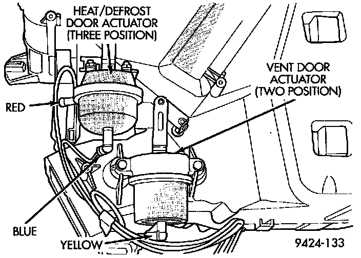
Fig 4 Recirc Duct/Vacuum Actuator:
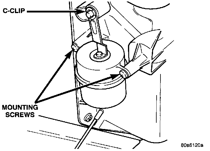
VACUUM ACTUATORS - MODE DOORS
The Heater (A/C) system has three actuators. The one located on the left side of the heater housing has two positions and a single vacuum hose attached to it. The second one is a three position actuator is located on the right side of the heater housing and has two (2) vacuum hoses attached to it. The third actuator is located on the recirc duct with a single vacuum hose attached to it.
The actuators can be tested and/or replaced without having to remove the heater housing.
The two position actuator's function is to direct the incoming air through the (A/C) vent ducts or the heat/defrost ducts.
The three position actuator's function is to direct the ratio of air going to the heater/defrost ducts:
- Position one allows 80 percent floor air and 20 percent defrost air.
- Position two allows 50 percent floor air and 50 percent defrost air.
- Position three allows 20 percent floor air and 80 percent defrost air.
The recirc door vacuum actuator function is to allow a mixture of fresh and recirculated air to be utilized by the system.
CIRCUIT OPERATION
A/C Operation
Operation of the A/C system is controlled by three switches which are wired in series and the Powertrain Control Module (PCM). When the operator turns the mode switch to the A/C position, a ground path is completed from the PCM (cavity C23) through the CLOSED dual pressure cut-out switch (circuit C20), thermostatic switch (circuit C21), and A/C switch (circuit C12) to circuit Z8. Circuit Z8 is connected to ground.
The PCM interprets this request and supplies a ground path for the A/C compressor clutch relay on circuit C13. Power for the A/C compressor clutch relay is supplied on circuit F12. This circuit is HOT in the RUN position only and is protected by a 10 amp fuse located in cavity 10 of the fuse block.
Power for the fuse is supplied on circuit A21 and A1. The A1 circuit is protected by a 40 amp fuse located in cavity 19 of the Power Distribution Center (PDC).
When the PCM grounds circuit C13, contacts in the relay CLOSE connecting circuits A17 and C3. The A17 circuit is a direct battery feed and protected by a 15 amp fuse located in cavity 2 of the PDC.
Circuit C3 connects from the relay to the A/C compressor clutch.
The A/C compressor clutch receives this voltage and creates a magnetic field energizing the clutch. Ground for the coil is provided on circuit Z1.
The connector at the A/C compressor has a diode located in it. This diode is used to control the induced voltage resulting from the magnetic field collapsing when the clutch is disengaged. The diode provides a path for the voltage to protect other components and systems.
The A/C compressor clutch relay is also used by the PCM to disengage the compressor in a wide open throttle (W.O.T) condition.
When the A/C system is in operation the PCM also operates the radiator fans.