Steering Column Code
P0562-BATTERY VOLTAGE LOW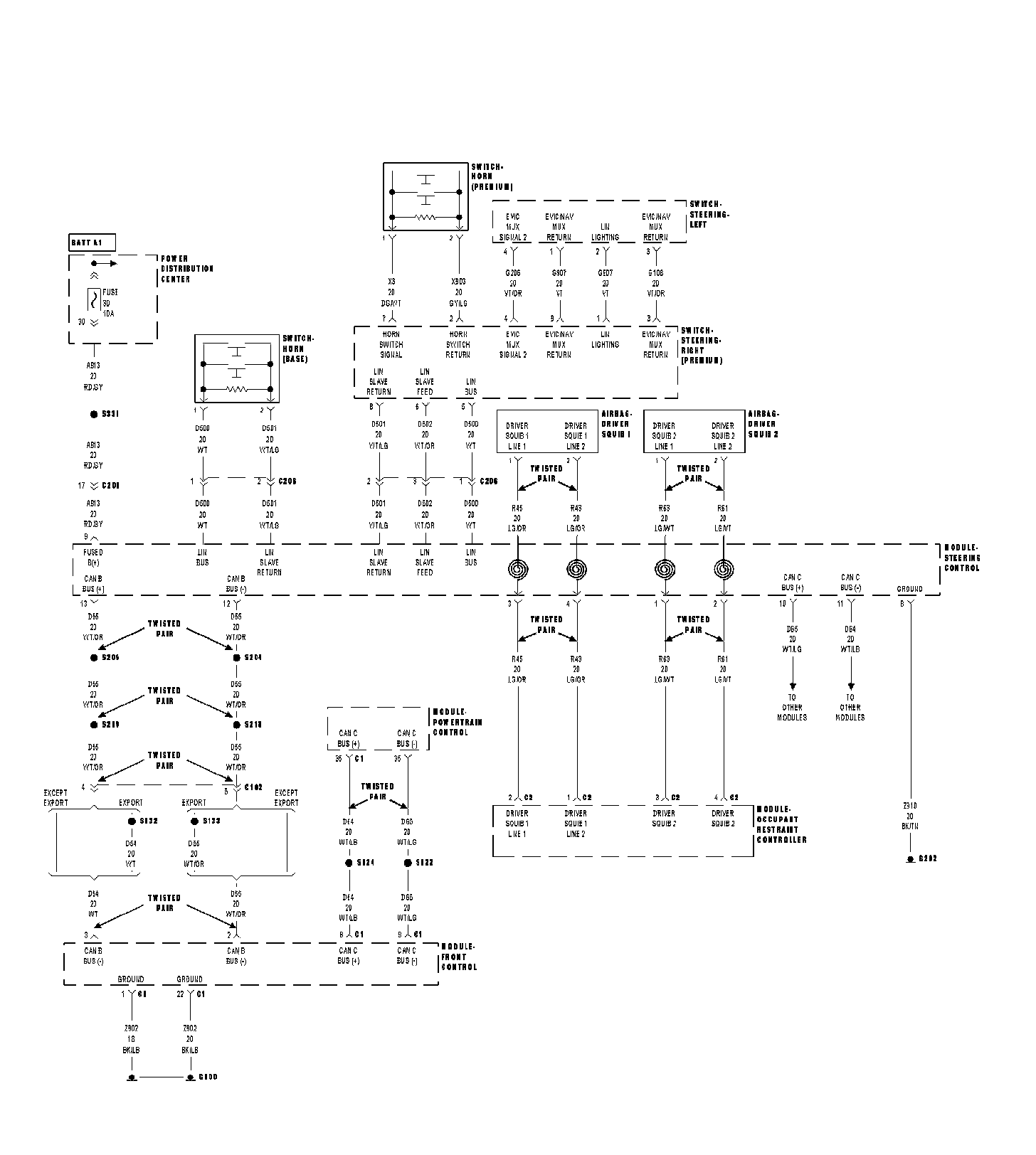
When Monitored
Continuously.
Set Condition
If the voltage to the Steering Column Control Module (SCCM) is below 8.5 volts for more than one minute.
Possible Causes
- RELATED DTC(S) PRESENT IN PCM
- INTERMITTENT BATTERY VOLTAGE LOW DTC
- (A913) FUSED B(+) CIRCUIT HIGH RESISTANCE
- (Z910) GROUND CIRCUIT HIGH RESISTANCE
- STEERING COLUMN CONTROL MODULE (SCCM)
Diagnostic Test
1. RELATED DTC(S) PRESENT IN PCM
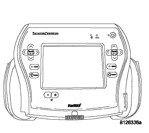
Ignition on, engine not running.
With the scan tool, select View DTCs in the Powertrain Control Module.
Are there any charging system or related battery voltage DTCs present in the PCM?
Yes >> Refer to the appropriate symptom in the Driveability category.
No >> Go to 2
2. DTC STATUS IS ACTIVE
With the scan tool, select View DTCs in the Steering Column Control Module.
Is the DTC status Active at this time?
Yes >> Go to 3
No >> Go to 5
3. (A913) FUSED B(+) CIRCUIT HIGH RESISTANCE
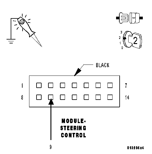
Turn the ignition off.
Remove the Steering Column Control Module in accordance with the Service Information.
Turn the ignition on.
Using a 12-volt test light connected to ground, check the (A913) Fused B(+) circuit in the Steering Column Control Module harness connector.
NOTE: The test light must illuminate brightly. Compare the brightness to that of a direct connection to the battery.
Does the test light illuminate brightly?
Yes >> Go to 4
No >> Repair the (A913) Fused B(+) circuit.
4. (Z910) GROUND CIRCUIT HIGH RESISTANCE
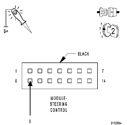
Using a 12-volt test light connected to 12-volts, check the (Z910) Ground circuit in the Steering Column Control Module harness connector.
NOTE: The test light must illuminate brightly. Compare the brightness to that of a direct connection to the battery.
Does the test light illuminate brightly?
Yes >> Replace the Steering Column Control Module in accordance with the Service Information.
No >> Repair the (Z910) Ground circuit.
5. INTERMITTENT BATTERY VOLTAGE LOW DTC
The conditions necessary to set this DTC are not present at this time.
Using the wiring diagram/schematic as a guide, inspect the wiring and connectors.
While monitoring the scan tool data relative to this circuit, wiggle test the wiring and connectors.
Look for the data to change or for the DTC to reset during the wiggle test.
Were any problems found?
Yes >> Repair as necessary.
No >> Test complete.