Differential Assembly: Adjustments
PINION DEPTH-BEARING PRELOAD-GEAR BACKLASH
PINION GEAR DEPTH
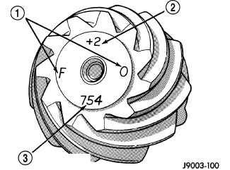
Ring and pinion gears match set number (3) and production number (1) are etched on the gears. A pinion depth variance number (2) is also etched on the gear, this will be a plus (+), minus (-) or zero (0). This number is the amount (in thousandths of an inch) the depth varies from the standard depth setting of a pinion etched with a (0).
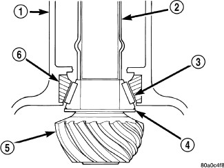
Compensation for pinion depth variance is achieved with select shims (4) located under inner pinion bearing cone (3). Pinion bearing preload is maintained through the use of a collapsible spacer (2).
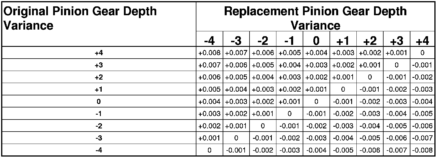
If a new gear set is being installed, note the depth variance etched into both the original and replacement pinion gear. Add or subtract the thickness of the original depth shims to compensate for the difference in the depth variances. Refer to the Depth Variance charts.
Note where Old and New Pinion Marking columns intersect. Intersecting figure represents plus or minus amount needed.
Note the etched number on the face of the drive pinion gear (-1, -2, 0, +1, +2, etc.). The numbers represent thousands of an inch deviation from the standard. If the number is negative, add that value to the required thickness of the depth shim(s). If the number is positive, subtract that value from the thickness of the depth shim(s). If the number is 0, no change is necessary. Refer to the Pinion Gear Depth Variance Chart.
PINION DEPTH MEASUREMENT
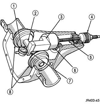
Measurements are taken with pinion cups and pinion bearings installed in housing. Take measurements with a Pinion Gauge Set, Arbor Discs 6927A (8) and Dial Indicator C-3339A (1).
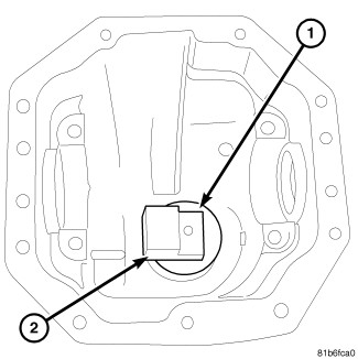
1. Assemble Pinion Block 8144 (1), Pinion Height Block 6739 (2), and rear pinion bearing onto Screw 6741.
2. Insert assembled height gauge components, rear bearing and screw into differential housing through pinion bearing cups.
3. Install front pinion bearing and Cone 6740. Tighten cone-nut until Torque To Rotate the screw is 2.0 Nm (18 in. lbs.).
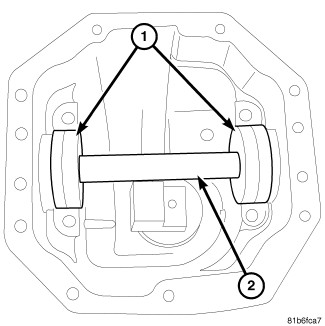
4. Place Arbor Disc 6927A (1) on Arbor D-115-3 (2) in position in differential housing side bearing cradles.
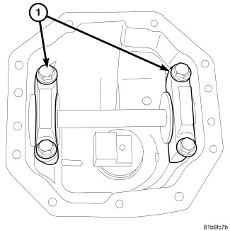
5. Install differential bearing caps on Arbor Discs. Tighten cap bolts to 88 Nm (65 in. lbs.).
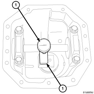
6. Slide dial indicator (1) probe across the gap between the pinion height block (2) and the arbor bar while holding scooter block against the pinion height block. Slide dial probe to the crest of the arbor bar and record the highest reading.
7. Select a shim equal to the dial indicator reading plus or minus the pinion gear depth variance number marked on the pinion gear. For example, if the depth variance is -2, add 0.002 in. to the dial indicator reading. If the depth variance is +2, subtract 0.002 in. to the dial indicator reading.
DIFFERENTIAL BEARING PRELOAD AND GEAR BACKLASH
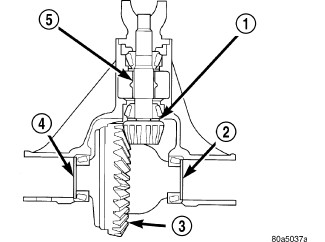
Before measuring differential bearing preload and gear backlash, pinion gear depth must be established and pinion gear ready for installation. Pinion gear depth is essential to establishing gear backlash and tooth contact patterns.
Differential bearing preload and gear backlash is achieved with selective shims (2) (4) located between the differential bearing cups and differential housing. Shim thickness is determined using Dummy Bearings 6929A in place of the differential side bearings and preload shims.
SHIM SELECTION
1. Remove differential side bearings from differential case.
2. Install ring gear on differential case and tighten bolts to specification.
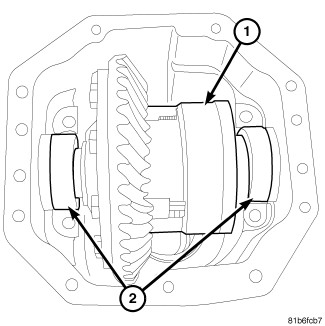
3. Install differential (1) with Dummy Bearings 6929A (2) into differential housing.
4. Install bearing caps and install bolts snug.
5. Seat differential dummy bearings to each side of the housing with a dead-blow hammer.
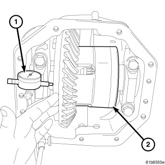
6. Attach a dial indicator C-3339A (1) to a stud and position indicator plunger on flat surface between the ring gear bolts.
7. Zero dial indicator (1) while holding the differential case (2) to the pinion gear side of differential housing.
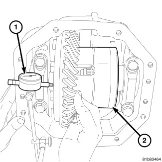
8. Push differential case to ring gear side of the housing.
9. Record dial indicator (1) reading while holding the differential case (2) to the ring gear side of the housing.
10. Add 0.2 mm (0.008 in.) to the recorded dial indicator reading. This is the total shim thickness needed to preload the new differential bearings.
11. Remove differential with dummy bearings from the housing.
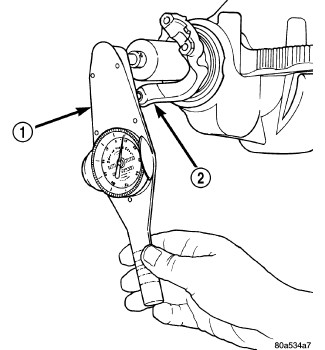
12. Install pinion gear in differential housing and establish pinion torque to rotating (2) with an inch pound torque wrench (1).
13. Install differential case with Dummy Bearings 6929A into the housing. Install bearing caps and tighten bolts snug.
14. Seat dummy bearing to the ring gear side with a dead-blow hammer.
15. Position dial indicator (1) plunger on a flat surface between the ring gear bolts.
16. Zero dial indicator (1) while holding the differential case (2) to the pinion gear side of differential housing.
17. Push differential case to ring gear side of the housing.
18. Record dial indicator (1) reading while holding the differential case (2) to the ring gear side of the housing.
19. Subtract 0.05 mm (0.002 in.) from the dial indicator reading or ring gear backlash. This total is the shim thickness needed on the ring gear side of the differential housing. Subtract the ring gear side shim thickness from the total preload shim thickness. The remainder is the shim thickness needed on the pinion gear side of the differential housing.
20. Remove dial indicator, differential case and dummy bearings from differential housing.
21. Install differential case with bearings and shims into differential housing.
BACKLASH MEASUREMENT
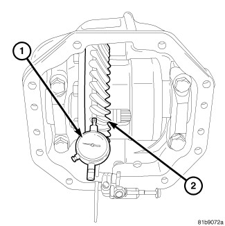
1. Rotate the differential case several times to seat the side bearings.
2. Position dial indicator (1) plunger against a ring gear tooth (2).
3. Push and hold ring gear upward while not allowing the pinion gear to rotate.
4. Zero dial indicator (1).
5. Push and hold ring gear downward while holding pinion gear stationary. Dial indicator reading should be between 0.102 - 0.152 mm (0.004 in. - 0.006 in.).
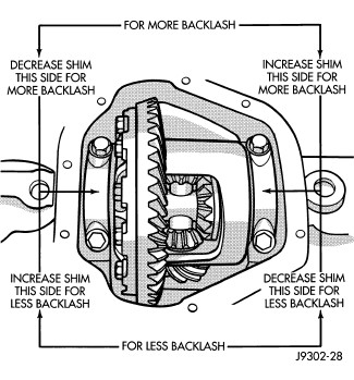
6. If backlash is not within specifications transfer the necessary amount of shim thickness from one side of the differential housing to the other.
7. Verify differential case and ring gear runout by measuring ring to pinion gear backlash at several locations around the ring gear. Readings should not vary more than 0.05 mm (0.002 in.). If readings vary more than specified, the ring gear or the differential case is defective.
After the proper backlash is achieved, perform Gear Contact Pattern Analysis procedure.
GEAR CONTACT PATTERN
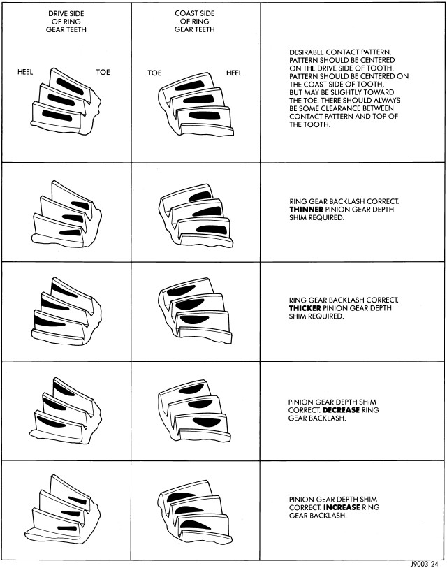
The ring and pinion gear teeth contact patterns will show if the pinion gear depth is correct in the differential housing. It will also show if the ring gear backlash has been adjusted correctly. The backlash can be adjusted within specifications to achieve desired tooth contact patterns.
1. Apply a thin coat of hydrated ferric oxide, or equivalent, to the drive and coast side of the ring gear teeth.
2. Wrap, twist, and hold a shop towel around the pinion yoke to increase the turning resistance of the pinion gear. This will provide a more distinct contact pattern.
3. Using a boxed end wrench on a ring gear bolt, Rotate the differential case one complete revolution in both directions while a load is being applied from shop towel.
The areas on the ring gear teeth with the greatest degree of contact against the pinion gear teeth will squeegee the compound to the areas with the least amount of contact. Note and compare patterns on the ring gear teeth to Gear Tooth Contact Pattern chart and adjust pinion depth and gear backlash as necessary.