Instrument Panel Removal
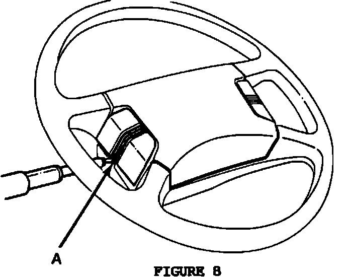
FIGURE 8:
1. Disconnect the battery.
2. Remove the lower trim covers of the left and right rocker panels.
3. Remove the 2 screws (A) to remove the steering wheel pad (Figure 8).
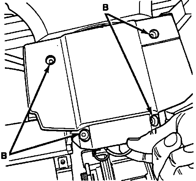
FIGURE 9:
4. Remove the steering wheel.
5. Remove the 4 screws (B) and remove the 2 steering-wheel half shells (Figure 9).
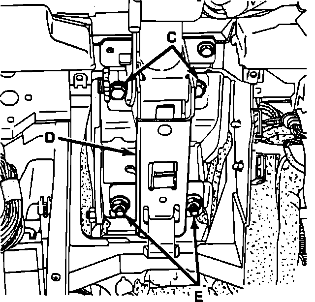
FIGURE 10:
6. Remove the fuse panel cover.
7. Remove the 2 screws (C) which fasten the steering column (D) (Figure 10).
8. Loosen the 2 nuts (E) (Figure 10).
FIGURE 11:
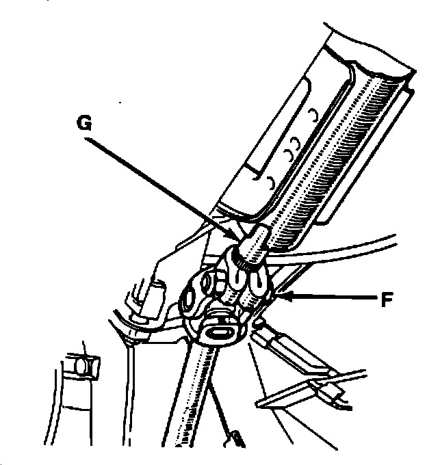
9. Remove the bolt (F) which fastens the steering column universal joint on the steering column (G) (Figure 11).
FIGURE 12:
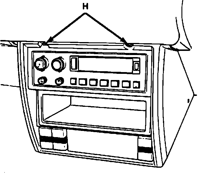
10. To remove the radio, remove the 2 screws (H) which hold the radio trim cover (Figure 12).
FIGURE 13:
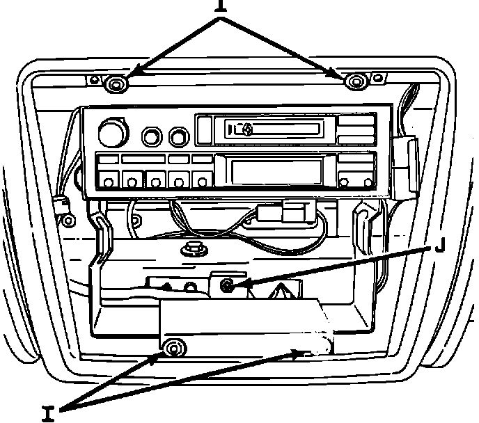
11. Remove rivets (I) and screw (J) (Figure 13).
FIGURE 14:
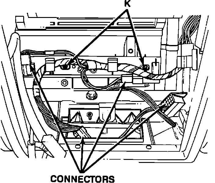
12. Disconnect the connector, the ground connection and the antenna and remove the radio.
13. Remove the 2 fastening screws (K) of the harness bracket (Figure 14).
14. Unclip the connectors attached to the harness and the center console connector (Figure 14).
FIGURE 15:
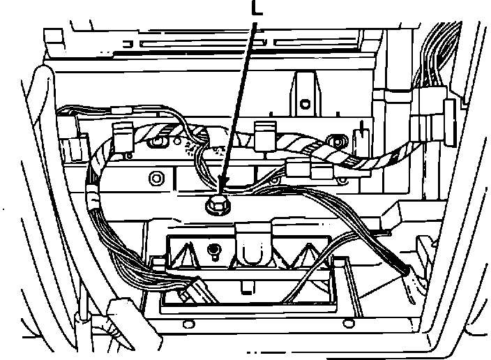
15. Remove the center fastening screw (L) of the instrument panel (Figure 15).
FIGURE 16:
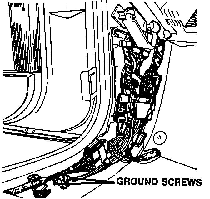
FIGURE 17:
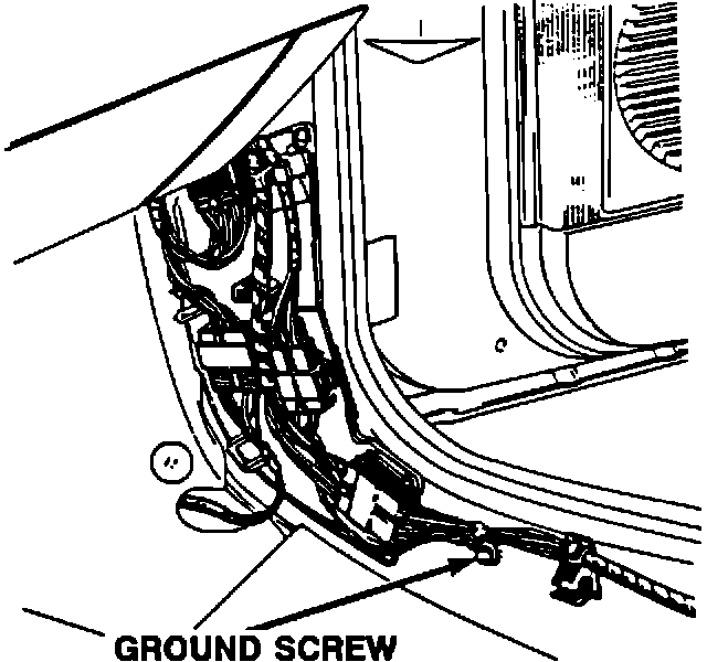
16. Unclip the front hinge pillar connectors and remove the 3 ground connection fastening screws: 2 on the left side, (Figure 16), 1 on the right side, (Figure 17).
FIGURE 18:
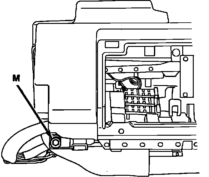
17. Remove the 2 (right and left sides) lower fastening screws (M) of the instrument panel (Figure 18).
18. Unclip the parking brake warning light connector located behind the toe board sound-proofing pad.
19. Reach under the instrument panel to unclip the speedometer cable from the base of the speedometer.
FIGURE 19:
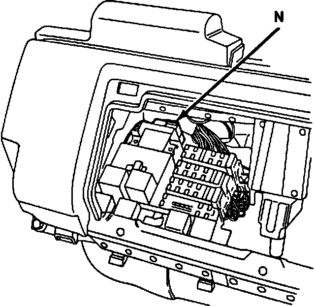
20. Unclip the connector (N) of the windshield-wiper harness (Figure 19).
FIGURE 20:
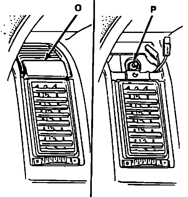
21. Unclip the 2 covers (0) (Figure 20) and remove the 2 screws which fasten the speaker brackets, located at the rear.
22. Disconnect and remove the speakers.
23. Remove the 2 upper fastening nuts (P) and remove the instrument panel (Figure 20).